About the concept and the universal nodes invented by UC4H:
„Having a CAN bus with daisy chained universal nodes … is the most appealing technology that most of us are waiting for years !! I raise my hand as a … champion of this concept.“ (ref)
Want to know about the latest development? … see here 🙂
ArduCopter and UAVCAN 2019: The ALL-UC4H Copter … see here 🙂
The
UAVCAN has been made available quite some time ago, in order to bring CAN to drones. The CAN bus is renowned for it’s extreme reliability and is thus attractive for application in drones. However, to the day I think it is fair to say that only few UAVCAN devices have become available, and those which are, are clearly for the professional market, at least price-wise. So, I set out to change that, and started the
The project presented me with initial challenges which made me considering to quit more than once. At this point I want to express my deepest thanks to Pavel, for the tremendous work he put into UAVCAN, and for not giving up answering my early questions. Thank you so much, sir! 🙂
The project has grown considerably and now consists of many pieces:
- UC4H GPS-Magnetometer-Barometer
- UC4H PowerBrick
- UC4H ESC-Actuator
- UC4H RangeFinder
- UC4H Notifiers: Notify, Display, OreoLEDs
- UC4H IndicatorLED
- UC4H UartBridge
- UC4H Airspeed-AngleOfAttack
- UC4H FunThing
- UC4H MAVLinkBridge
- UC4H Bootloader
- UC4H SLCAN Adapter
- UC4H Cube Carrier
If you want to
You also can
For the
Useful Links
- UC4H Github repository, hosting the firmware binaries, Eagle design files, and some more material.
- Mike’s thread CANbus for Ardupilot with UAVCAN and UC4H @ rcgropups.
- CAN Devices section @ ardupilot.discuss.
- Mike’s blog CANbus Quadcopter using UC4H : Son of FrankenSolo @ ardupilot.discuss.
- Patrick’s blog UAVCAN UART NODE ; adding 3 more Serial Ports to your Flight Controller with TUNNELING @ ardupilot.discuss.
- My article Drone CAN Bus Power Schemes.
First user demonstrating a successful flight using UC4H components:

TERMS OF USAGE
The material provided in the UC4H Github repository is subject to the following conditions. Firmware files: All firmwares are free (but not open source). Besides unlimited private use you are also granted the permission to use them for commercial purposes under the condition that (1) you don’t modify the firmware, e.g. remove or change copyright statements, (2) provide it for free, i.e. don’t charge any explicit or implicit fees to your customers, and (3) correctly and clearly cite the origin of the firmware and the project web page in any product documentation or web page. Hardware files: All hardware, for which material is provided, is open source hardware, under the terms of the TAPR Open Hardware License as published by the Free Hardware Foundation, see https://www.tapr.org/ohl.html. The TAPR license explicitly permits essentially unlimited commercial use, with only few conditions such as that copyright logos are not removed.
See also the UC4H Vendor Partner Program.
Usage Information
For me, the UC4H nodes are working great; I didn’t had a single incident because of using them. There are of course always little things which could be improved, but overall I’m very satisfied. It’s working, I like my UC4H-ized copter, and in this sense the project has accomplished its goals. I’d like to leave some comments on its applicability.
In principle, the UC4H nodes can be used in any UAVCAN network. That’s the idea of UAVCAN. I only can speak for ArduPilot, however, since that’s what I’m using. With ArduPilot, these restrictions apply:
ArduPilot
ArduPilot master has recently seen substantial changes in the UAVCAN section and is not totally compatible with earlier ArduPilot versions. So, I currently would recommend ArduCopter 3.6.x, to which I refer here.
ArduPilot 3.6 supports the GPS, magnetometer, barometer, ESC, actuator, and IndicatorLED UAVCAN messages. With native ArduPilot you can thus use the UC4H GPS-Magnetometer-Barometer and UC4H ESC-Actuator nodes out of the box, they are fully compatible with ArduPilot.
BetaCopter 3.6
This is a fork of ArduCopter 3.6, and has compiled binaries for v2 (Pixhawk), v3 (3DR Solo, Pixhawk2), and v4 (Pixracer) flight controllers. It has full support for the whole family of UC4H nodes, as well as the STorM32 gimbal controller. Thus, if you want to make best use of the potential of the UC4H project, then you want to flash BetaCopter 3.6 (you need the 'u' version, e.g. BetaCopter 3.6.1 v0.14u, see the github repo for details).
The code additions in BetaCopter are basically vehicle independent, i.e., it should be possible to compile the source also for other vehicles such as planes and rovers with only minor changes, and it therefore probably should be called BetaPilot. However, I’m using only copter, and only can test for copter, and for (only) that reason I speak of only copter. 🙂
The BetaCopter sources and binaries are available from my github repo: here.
The „feature matrix“ thus looks like this:
| ArduCopter | BetaCopter | |
|---|---|---|
| GPS | x | x |
| dual UAVCAN GPS | – | x |
| Magnetometer | x | x |
| Barometer | x | x |
| PowerBrick (high-precision charge & energy counting, multi-cell voltage monitoring) |
– | x |
| ESC | x | x |
| ESC Telemetry (DataFlash, BattMonitor, MAVLink) |
– | x |
| Actuator (= Servo) | x | x |
| RangeFinder | – | x |
| UART Tunnels | – | 3 x |
| Notify | – | x |
| Display | – | x |
| OreoLED | – | x |
| IndicatorLED | x | x |
| Airspeed | x (1) | – (2) |
| Angle-of-Attack | – | – (2) |
| STorM32 | – | x |
| MavlinkBridge | x | x |
(1) Not available in ArduCopter 3.6, only in ArduPilot master.
(2) The UC4H Airspeed sensor is not supported by current BetaCopter; there exists a special branch for it however, which is recommended for testing.
The UC4H SLCAN adapter is of course independent on any flight controller support, and is in fact also independent on UAVCAN. It thus can be used in any CAN bus network.
General Building Information
Building the UC4H nodes is not very difficult, and generally two approaches are available:
Print Boards
For all nodes I have designed suitable PCBs, which allow nice and convenient builds. Nearly all of the nodes can be realized using the
The boards may look difficult to build, and for those who never have done SMD soldering, it probably is, but when using solder paste and a hot-air station (good ones, such as the 858D, are available for ca $35) it is really much simpler to do than you might think at first. It’s all just about practicing it.
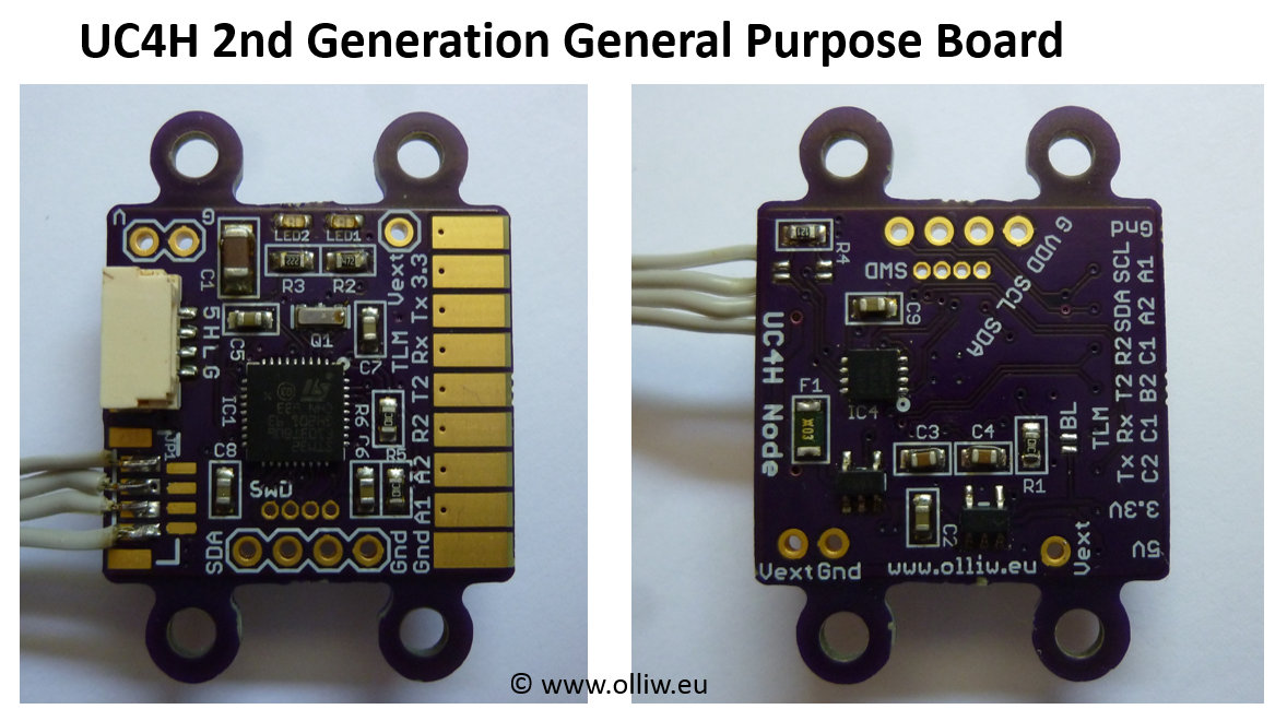
The „1st generation“ versions of these PCBs all provide a fuse & diode protection in accordance with the standard. In addition, they use the TJA1051 CAN transceiver, a so-called 3rd generation CAN transceiver, with state-of-the-art protection and reliability features. These chips can however be destroyed by overvoltages on the 5 V CAN bus, which should never happen since it should be clear that 5 V electronics should not be exposed to higher voltages, but in practice such things appear to happen. 🙂 I thus started a rehaul of my PCB layouts, which I call „2nd generation UC4H nodes“, which adds overvoltage and reverse voltage protection, and makes the UC4H nodes ultra robust. An example is the 2nd generation General-purpose UC4H Node shown in the above picture, but also the UC4H PowerBrick and UC4H ESC KISS Carrier boards have been reworked already.
DIY
One of the promises of the UC4H project is to bring UAVCAN to the hobbyist, which means dirty cheap and hacky, right? And in fact, each of the nodes, except of the UC4H PowerBrick, can also be build using cheaply and widely available STM32F103C8/CB and CAN transceiver modules. The result of course doesn’t look as snugly as with a PCB, but it is incredibly simple, and cheap, and works equally well.
For instance, I’ve ordered this, also known as the „bluepill“, STM32F103C8 development board at $1.80, and this SN65HVD230 CAN transceiver module for $1.89. The cost for a UC4H node can thus be as low as $3.69. Cool, eh.
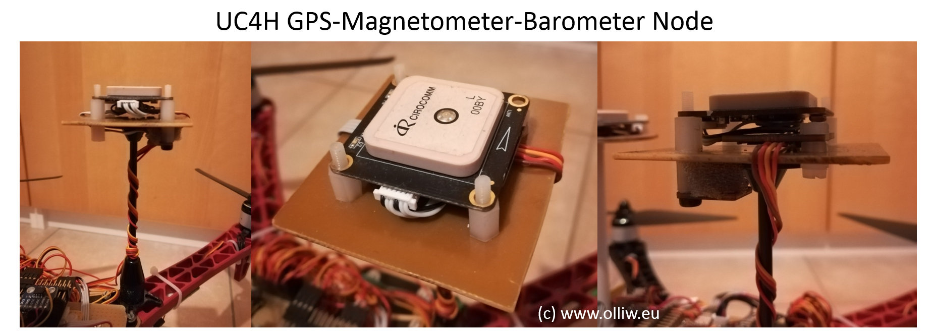
UC4H GPS-Magnetometer-Barometer Node
This had been the very first UC4H node, introduced in early 2017, starting off as the UC4H GPS-Magnetometer node. In the meantime it however has seen the addition of the tunnel, indicator LED, and barometer, and is now referred to as the UC4H GPS-Magnetometer-Barometer node. So, if you find a UC4H GPS-Magnetometer being mentioned somewhere, it is this node here. 🙂
The UC4H GPS-Magnetometer-Barometer node provides a bridge for connecting any of the widely and relatively cheaply available ublox M8
You may ask: Why should one want to do this? I did it for several reasons:
- I really was annoyed by the I2C wires usually used for the magnetometer. I found them to be the most unreliable connections, repeatedly causing me troubles.
- No issues with running out of UART ports on the flight controller anymore.
- It leads to a cleaner wiring. Instead of 7 wires only 4 are needed. Also, fewer wires go to the flight controller, especially if more UAVCAN units are used. This can help with damping flight controller vibrations, and avoids having to deal with many different connector types.
- It’s just cool. 🙂
Good and cheap GPS modules are for instance the Hobbyking UBLOX Micro M8N GPS Compass or the Drotek Ublox NEO-M8N GPS + HMC5983 Compass modules.
However, from the scheme it should be clear that
The UC4H GPS-Magnetometer-Barometer node also allows us to connect a
The UC4H GPS-Magnetometer-Barometer firmware can be configured, by setting of a parameter, to behave as a UC4H GPS, UC4H Magnetometer, or UC4H Barometer node, or any combination thereof. For instance, it can become a UC4H GPS-Magnetometer node. This configurability is very useful in case you have several of them in your system – which is quite likely, right?
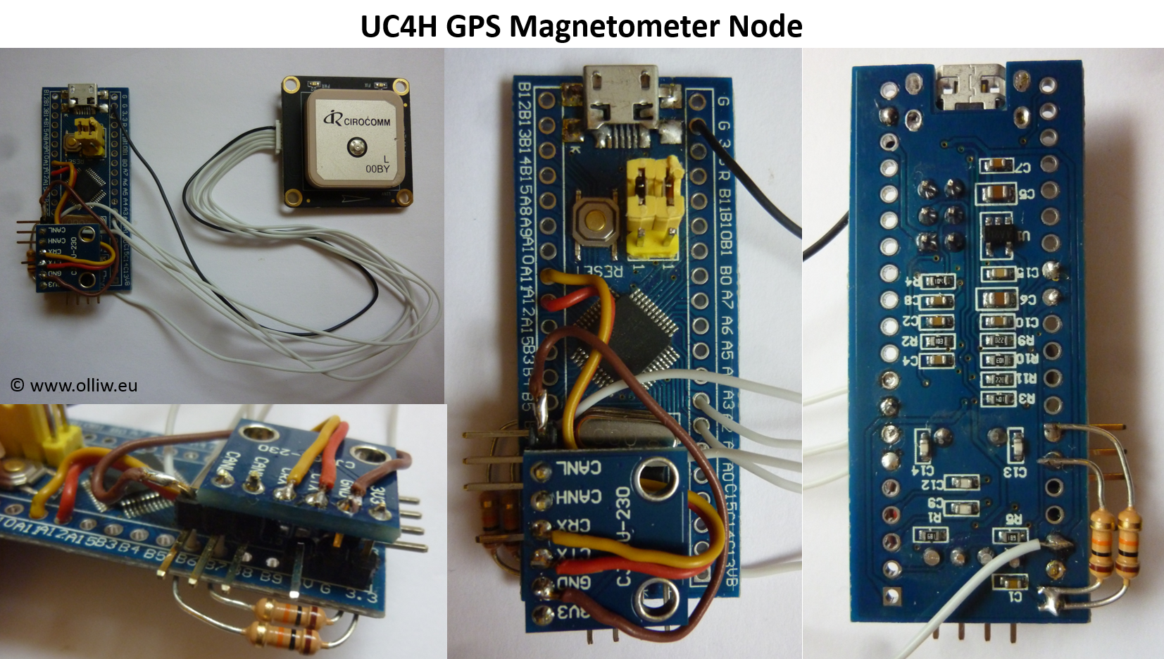
Builds
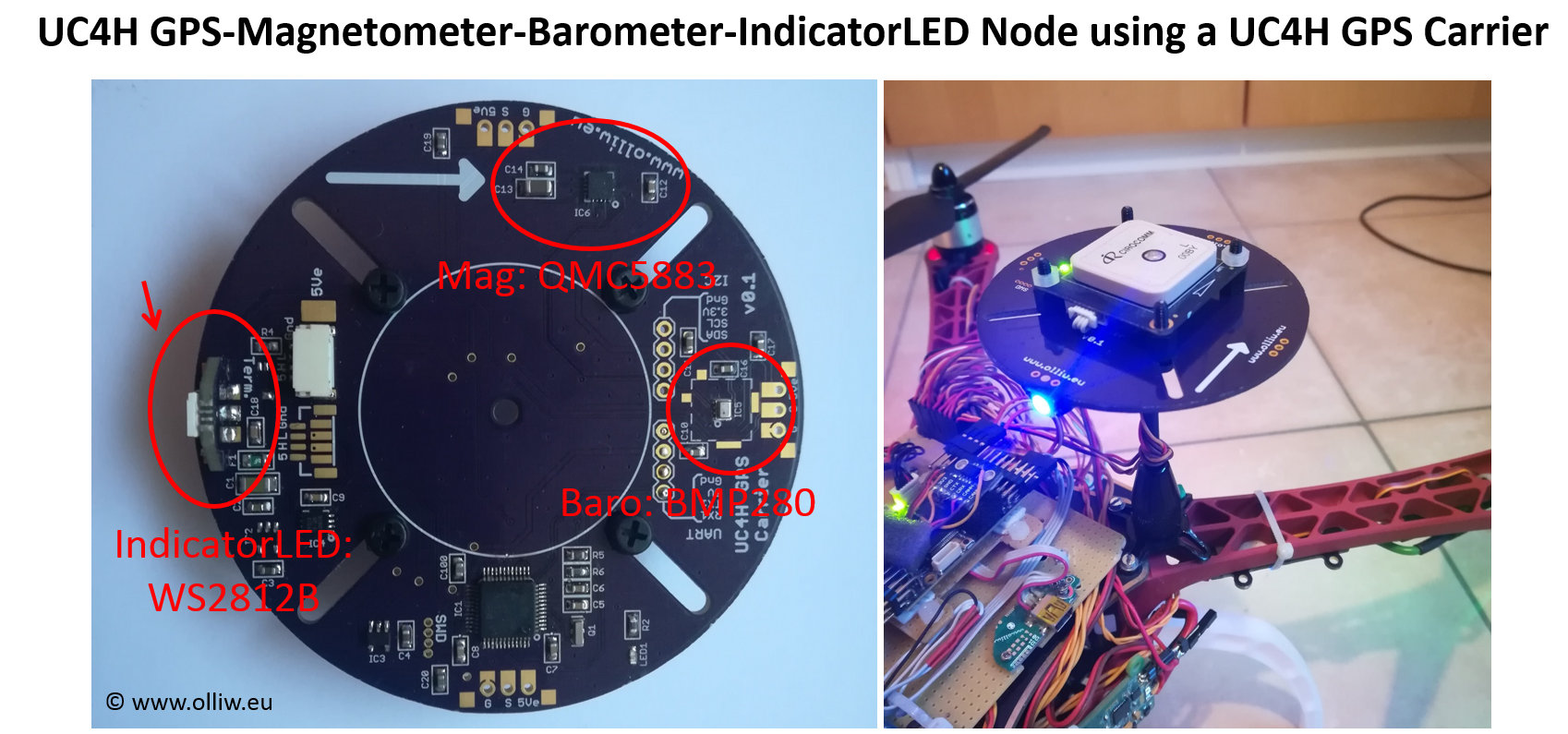
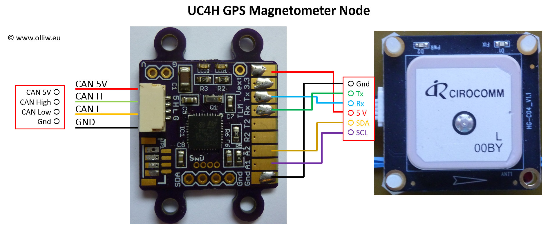
The node can be build in several ways. The best option is undoubtedly using a UC4H GPS Carrier board, as it was shown in the previous picture. The node can also be build using the general-purpose UC4H node, which you can see in the next picture. It also sketches the connection diagram, here for a Hobbyking GPS and magnetometer module. An additional barometer module would of course also go to the I2C connections, in parallel to the magnetometer, and the signal line of an WS2812B IndicatorLED would go to pad B2. As a practical example, the second-next picture shows my build of an UC4H GPS-Mag-Baro node, which uses the aforementioned general-purpose UC4H node and Hobbyking GPS and magnetometer module, plus a BMP280 module.
The UC4H GPS-Magnetometer-Barometer node can of course also be build using the DIY approach. With the components suggested in the above. The cost for converting a GPS module into a fully fledged UC4H GPS-Magnetometer node can thus be only $4. It hardly could be any cheaper, right 🙂
Depending on the GPS/magnetometer module it can be necessary to add two pull-up resistors to the I2C lines. This is e.g. the case for the mentioned Hobbyking module. A general scheme and a practical build is shown here:

Documentation
Node Configuration Parameter
As mentioned, the node can be configured to present itself in different ways. The parameter which controls this is „Node Configuration“: It is a bitmask, where bit 0 enables the GPS functionality, bit 1 the magnetometer functionality, and bit 2 the barometer functionality:
1 = 0b001 = GPS
2 = 0b010 = magnetometer
4 = 0b100 = barometer
Per default its value is zero (= all enabled), and the node presents itself as UC4H GPS-Magnetometer-Barometer node, and all parameter fields are accessible. If this parameter is set to e.g. 3 = 1 + 2 = 0b011, the node presents itself as a UC4H GPS-Magnetometer node, and all parameter fields which are related to the barometer functionality are hidden and cannot be accessed. If the node should become a UC4H barometer node, a value of 4 would be written, and all parameter fields related to the GPS and magnetometer functionalities would be hidden. In order to get back to the default, just do an ERASE. Configuration changes need a restart of the node to become effective.
Screenshots of the parameters of the node in different configurations can be found here:
* https://github.com/olliw42/uavcan4hobbyists/tree/master/firmware%20binaries/parameter-screenshoots
Error Conditions
Generally, the health status becomes ERROR or CRITICAL only during start up, if a senor is not detected, but it does not change during operation. The heartbeat LED blinks fast if the health status is not OK. The conditions which lead to an error are:
* If MagneticFieldRate > 0 and if a magnetometer module could not be found during startup, then: ERROR
* If BaroRate > 0 and if a barometer module could not be found during startup, then: ERROR
* The handling of a GPS is different: If the tunnel is not activated (Uart1 ChannelID = -1), then the node waits until it detects a GPS, which is indicated by a mode INITIALIZATION. Once the GPS is detected and configured the mode will change to OPERATIONAL. Thus, if a GPS module cannot be found, this won’t raise an ERROR, but makes the node to stay in INITIALIZATION for indefinite.
General Info
An in detail disussion of the UC4H GPS-Magnetometer-Barometer’s design, configuration, and features can be found in this video:
Screenshots of the parameters of the node in different configurations can be found here:
* https://github.com/olliw42/uavcan4hobbyists/tree/master/firmware%20binaries/parameter-screenshoots
These chapters may also be of interest:
* Build Information
* Supported UAVCAN Messages
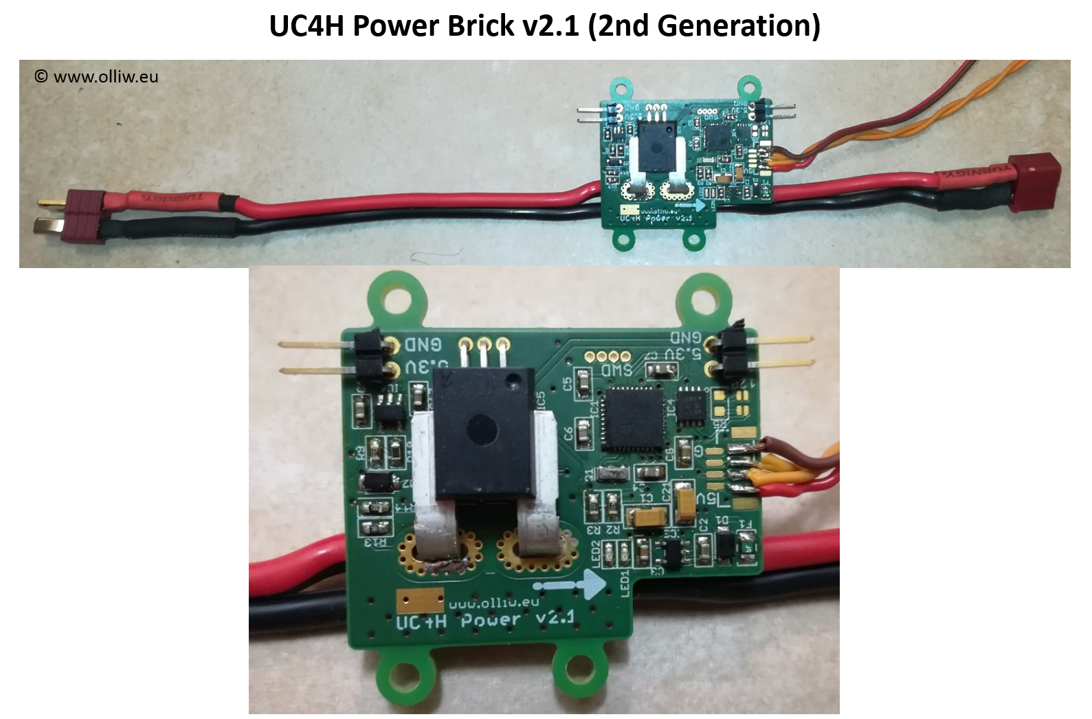
UC4H PowerBrick
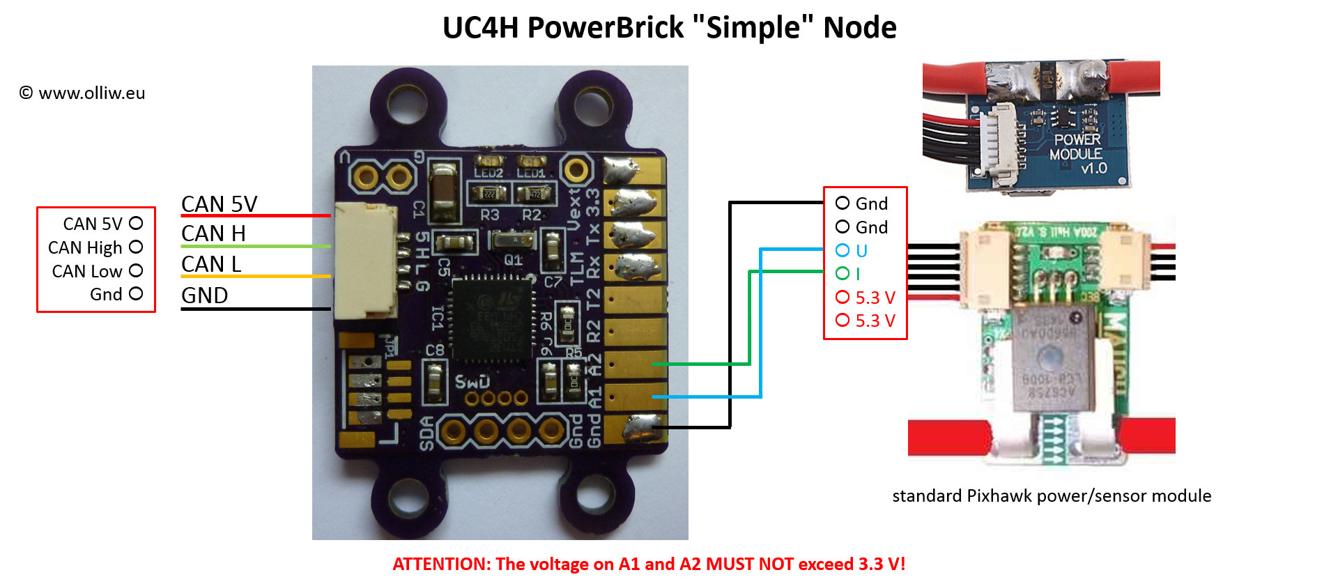
The UC4H PowerBrick combines measuring the voltage and current of the battery, and a 5.3 V/3 A power source for powering the copter electronics. It is thus a substitute for modules such as the common 3DR power module, the ACSP4/5/7 modules by AUAV/mRo, or the sensor and BEC modules by Mauch, but has much more to offer.
The UC4H PowerBrick has some top-notch features:
-
Uavcan: Well, obviously, that’s its major point. It emits the UC4H-specifc GenericBatteryInfo message at adjustable intervals. -
Low-noise Switch Regulator: I use the LT8610A which is good for 42 V and 3.5 A. It’s a member of the LT8610 family of regulators, which is also used by e.g. the ACSP series of AUAV/mRo. -
Hall Current Sensor: No lousy resistor shunt, Hall sensors are state-of-the art and should be standard. I use the ACS770, which is the successor of the well-known ACS758, which has been widely used in the drones area (see e.g. here), and offers slightly better specs. The ACS780/1 could also be worth a consideration, but it is a bit „trickier“ and less accurate. -
LDO Stabilized Voltage for the Hall Current Sensor: This is actually a point which I think has been overlooked in the design of available power modules using the ACS7xx sensors (e.g. here and here): The ACS7xx sensors are ratiometric. This means that when its supply voltage varies also the current sensor output signal varies proportionally. Thus, if the ACS7xx is directly powered from the 5.3 V source, as it is usually done, then any significant power drawn from the 5.3 V source will result in a drop of the measured current value, since the voltage will drop. In my tests a draw of 2 A led to a drop from 5.3 V to 5.0 V or 6%, and the current on the main line will be measured incorrectly by 6% – which is quite a lot. In the UC4H PowerBrick this is overcome by using an extra LDO regulator for sourcing the ACS7xx sensor, ensuring most precise current measurement. -
Precise Charge and Energy Calculation: This is another unique feature. Since the UC4H PowerBrick has its own microcontroller, it can determine the consumed charge (mAh) and consumed energy (Wh) much more precisely than would be possible otherwise. This is so because it can measure the current at a much higher rate and thus track current fluctuations much more precisely. Specifically, the node’s firmware measures the current at 1 kHz, which is several 100 times faster than with the currently available power bricks. -
Individual Cell Voltage Monitoring: The UC4H PowerBrick allows us to connect a FrSky lipo cell voltage sensor (MLVSS or FLVSS) for monitoring the battery cell voltages. I opted for this approach instead of adding such electronics to the UC4H PowerBrick board itself, since it deemed me more flexible (see also this blog post).
I do have the UC4H PowerBrick in permanent operation in my development copter since more than a year now, and it just works fantastic. No problems at all. I’m lov’in it 🙂
As a demonstration of the accuracy of the charge counting, which is achieved – routinely – with the UC4H PowerBrick, I’d like to show this one result:
- charge recorded by power brick: 4336 mAh (the flight log is here)
- charge shown by the charger: 4391 mAh
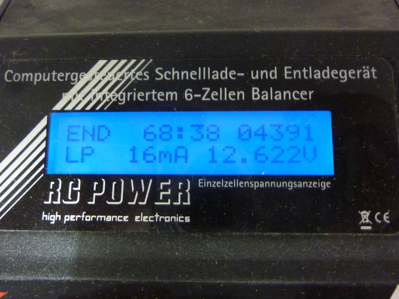
So, that is accurate to better than 1.5 %! And note: This is without any calibration of any sort! This level of accuracy of 1-2 % is achieved routinely, and is obviously substantially better than what one gets when using ArduPilot’s in-built charge counting.
If interested in in-depth bench tests of the UC4H PowerBrick to test its solid working, then you can find some reported here.
The UC4H PowerBrick emits the UC4H-specific uavcan.olliw.uc4h.GenericBatteryInfo message. It can be configured to emit the standard data type uavcan.equipment.power.BatteryInfo for compatibility reasons, but this is really not recommended since it deprives the UC4H PowerBrick of its best features.
Builds
The by far best way to build the UC4H PowerBrick is to use the dedictaed PCB shown in the above. However, it also can be build using the general-purpose UC4H node or the DIY bluepill approach in combination with the widely available standard Pixhawk stuff such as the 3DR powerbrick or MAUCH modules. However, with such a build one usually won’t achieve the full potential of the UC4H PowerBrick (unless on adds substiantial extra electronics to the build). The connection scheme for a DIY build using the general-purpose UC4H node is:
Documentation
An in detail disussion of the UC4H PowerBrick’s design, configuration, and features can be found in this video:
A screenshot of the parameters of the node can be found here:
* https://github.com/olliw42/uavcan4hobbyists/tree/master/firmware%20binaries/parameter-screenshoots
These chapters may also be of interest:
* Build Information
* Supported UAVCAN Messages
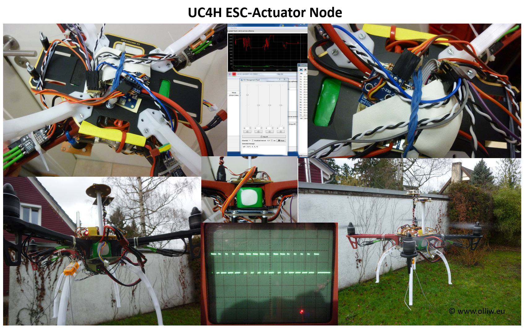
UC4H ESC-Actuator Node
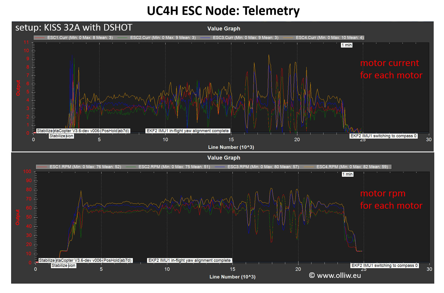
The UC4H ESC-Actuator node provides PWM or DSHOT signals for connecting ESCs and servos (= actuators), as well as telemetry feedback where possible. It offers up to six independent PWM/DSHOT outputs, which are controlled by the uavcan.equipment.esc.RawCommand or the uavcan.equipment.actuator.ArrayCommand data types, depending on the configuration of the output channels.
A major feature of the node, for the channels configured as ESC output, is to provide telemetry data about the status of the connected motors to the flight controller. For each enabled ESC output the node emits a uavcan.equipment.esc.Status data type. For DSHOT and telemetry capable ESCs (KISS, BLHeli_32) the telemetry data from the ESC are polled at an adjustable rate (default 5 Hz), and filled into the fields of the uavcan.equipment.esc.Status data type, yielding real-time data on temperature, voltage, current, and rpm for each motor. Furthermore, the telemetry data is used to feed a battery monitor, which provides additional data for checking the status of the power train.
As another great feature, the node comes with UC4H OreoLEDs support integrated, i.e. can drive the OreoLED strip of the arm associated with the ESC. This really makes it easy to add lightning to the copter with an unprecedented clean build.
In combination with suitable ESCs, the UC4H ESC-Actuator node thus offers these advantages:
- Uavcan: Well, obviously, that’s the major point. The cool thing about the concept presented here is that any ESC can be used, making available to UAVCAN a wide selection of excellent and cheap ESCs.
- Fast update rate and low latency: ArduCopter emits UAVCAN ESC commands at rates of up to 400 Hz. Due to the nature of the CAN bus, and the UC4H ESC node in DSHOT mode, the latency varies from ca. 160 – 300 us. This is significantly shorter than the 1-2 ms for the ordinary PWM signals.
- Real-time telemetry data: The availability of telemetry data for each motor individually is certainly another strong feature, which may open new possibilities not available to hobbyists before.
- OreoLEDs: It never was easier to build a copter with cool lightning.
The node has been extensively tested on the bench, and also has passed flight tests in both my development copter and a 3DR Solo (see here, here, and here). In both copters I do have them in routine operation for many months now.
Builds
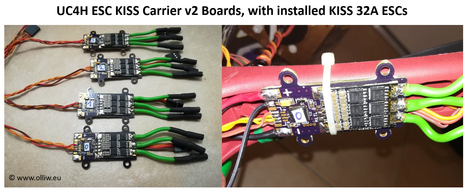
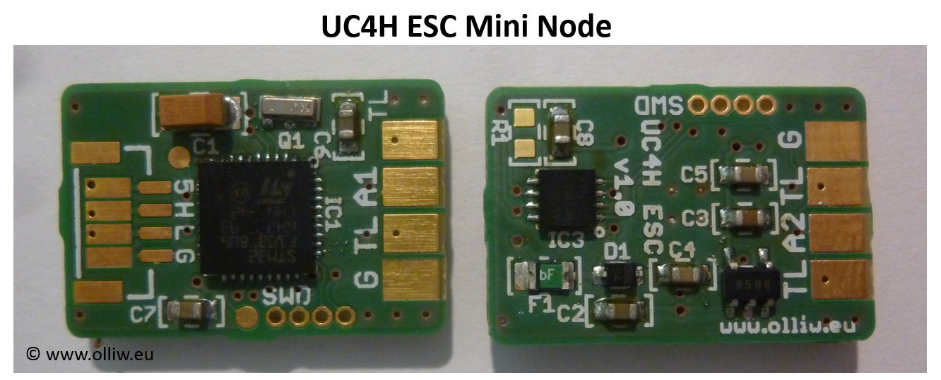
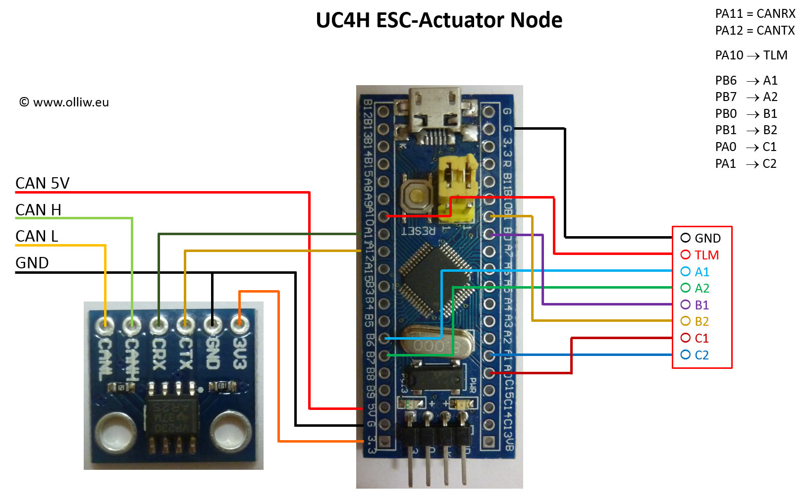
The node can be build in several ways. For ESCs, my clear favorite is the UC4H ESC KISS Carrier board, which is now also available in 2nd generation. The board is designed for carrying KISS 32A or 24A ESCs. I really like it and just can recommend it; IMHO the best option available. Also, the general-purpose UC4H node can be used, which then provides all six outputs, plus telemetry, plus OreoLED, depending on parameter settings. Furthermore, I have designed a UC4H ESC Mini PCB, which is only 21×14 mm in size, and which supports up to two ESCs (with DSHOT and telemetry of course). I have them in use e.g. in my 3DR Solo, for overcoming the motor pod issue of the stock 3DR Solo. Lastly, as usual, the node can be build using the CAN transceiver and STM32F103 development boards mentioned in previous chapters. A scheme is shown below.
Documentation
A brief description of the parameters of the node, and other info relevant for using and building the node, can be found here: https://www.rcgroups.com/forums/showpost.php?p=39144246&postcount=509
An in detail disussion of the UC4H ESC node telemetry features and OreoLEDs can be found in these two videos (for the configuration see the next sub chapter):
A screenshot of the parameters of the node can be found here:
* https://github.com/olliw42/uavcan4hobbyists/tree/master/firmware%20binaries/parameter-screenshoots
These chapters may also be of interest:
* Build Information
* Supported UAVCAN Messages
Configuration
The correct configuration of the UC4H ESC nodes is a bit tricky, since quite many parameters need to be set correctly, and the ArduPilot project doesn’t yet offer user-friendly UAVCAN node configuration methods. I provide two methods, a manual and a script-based configuration method.
The manual coinfiguration method is described in detail in the left video below.
In addition, a Python script was developed, which makes setting up the UC4H ESC nodes a piece of cake. It runs through all necessary steps almost automatically, requiring only minimal user input. The right video explains the required 3 basic steps, as well as the operation of an older version of the Python script. The latest script does it all; it can be found as usual in the UC4H Github repository.
UC4H RangeFinder Node
The UC4H RangeFinder node brings several range finders, currently the Benewake TFMini and the STMicroelectronics VL53L1x, to the CAN/UAVCAN bus.
Builds
As usual, the general-purpose UC4H node as well as the DIY bluepill approach can be used to build UC4H RangeFinder nodes. However, I have also designed some dedicated PCBs.
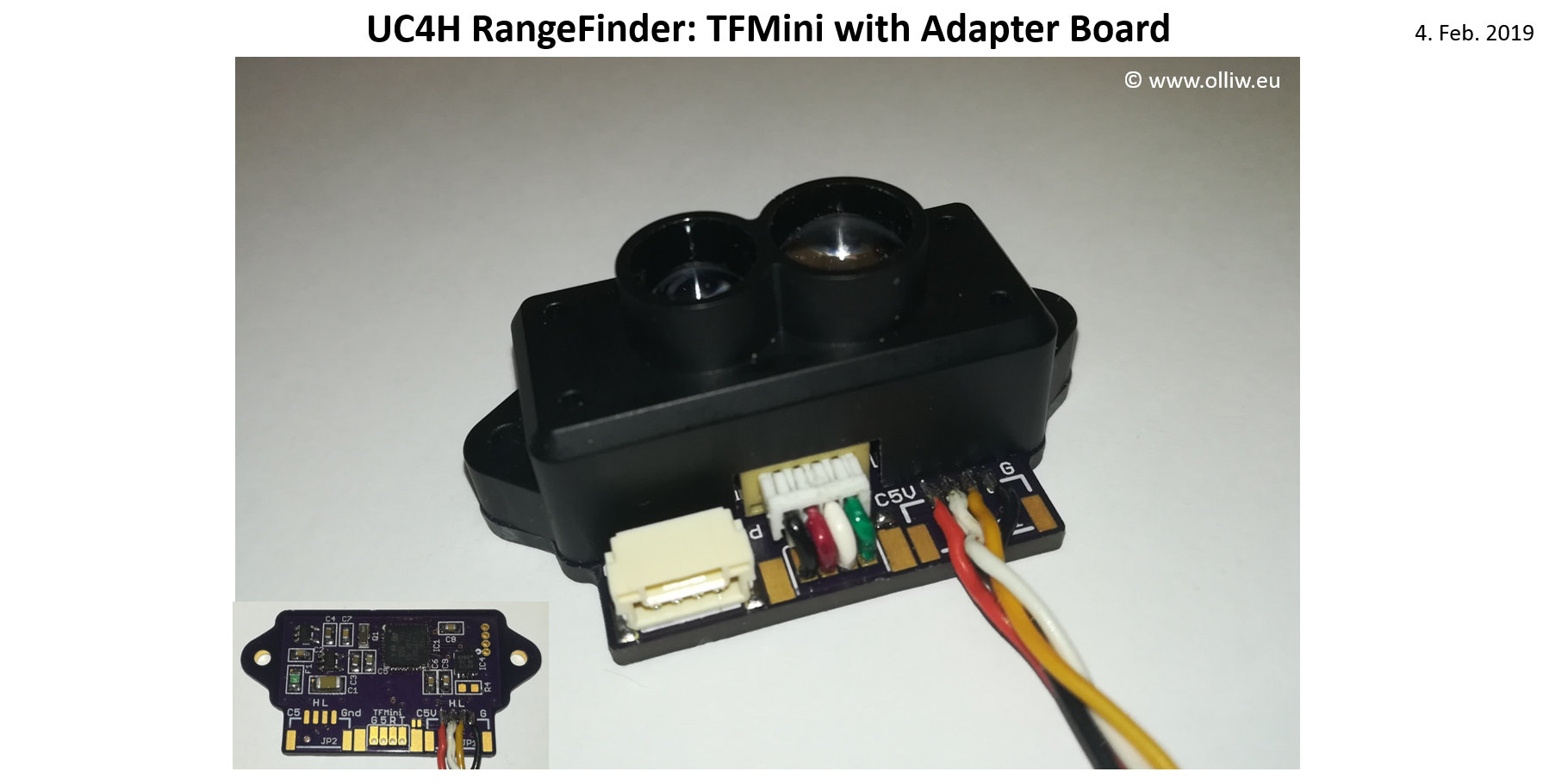
For the TFMini this is a cute little adapter board, shown in the next picture. The power supply for the TFMini needs some attention, since it requires quite some power, which can overload the available power on the 5 V CAN bus line. So, provide enough power!
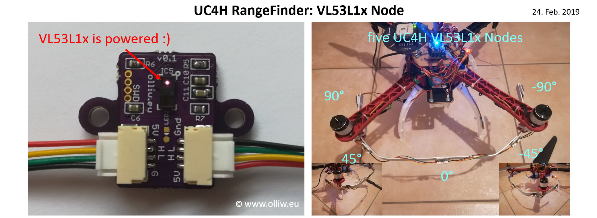
Also a PCB for building UC4H VL53L1x nodes is available, as shown in the next picture. It is quite small, which was possible also because I modified the electric scheme. It is as safe as the 2nd generation nodes, in terms of protections, but requires fewer parts. The UC4H VL53L1x nodes are currently the best option available for installing several or even many of these rangefinders on your vehicle, since they avoid the considerable tweaking pain of other approaches.
Documentation
The UC4H RangeFinder can be configured in a generic mode, in which it emits the uavcan.olliw.uc4h.Distance DSDL message, or in a tunnel mode, in which it works exactly like a UART bridge, using the tunnel.Broadcast DSDL message (see UC4H UartBridge Node).
The tunnel mode can be of interest for range finders which natively provide a UART port, such as the TFMini. This mode is activated by setting the parameters RangeRate = 0 and ChannelId to a value larger than -1. It is however not recommended in general, because of it consumes a much higher bandwidth on the CAN bus. This can be problematic when more range finders are used, which typically send data at high rates (the TFMin e.g. at 100 Hz).
The generic mode is activated whenever the parameter RangeRate is set to a nonzero value (10 or larger). In this case the node emits the uc4h.Distance message. It is very compact and hence allows for high data rates and/or many range finders on the CAN bus without clogging it.
It uses a concept I call extended Id. Normally, ArduPilot identifies the UAVCAN node to use by either the Node Id or an index, such as sensor_id, battery_id, actuator_id, and so on. For the uc4h.Distance message the identification should however be based on the Node Id, as well as on the information in the fields fixed_axis_pitch, fixed_axis_yaw, and sensor_sub_id. This concept makes configuration most user-friendly, since the sensor identification is based on information the user needs to enter anyhow and is intelligible (see BetaCopter for a reference implementation).
PS: This concept could/should be extended to all UAVCAN sensors, as it brings general advantages in terms of user-friendliness. 😉
An in detail disussion of the UC4H RangeFinder node can be found in this video:
A screenshot of the parameters of the node can be found here:
* https://github.com/olliw42/uavcan4hobbyists/tree/master/firmware%20binaries/parameter-screenshoots
These chapters may also be of interest:
* Build Information
* Supported UAVCAN Messages
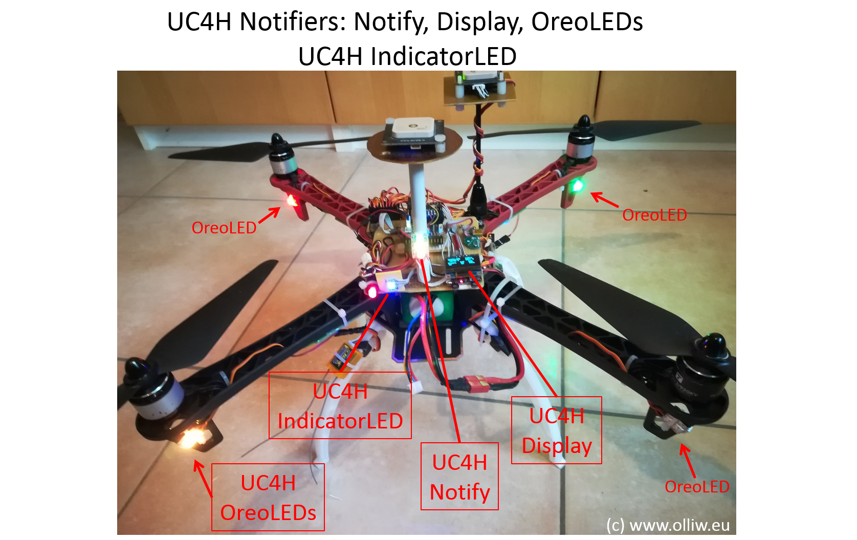
UC4H Notifier: Notify, Display, OreoLEDs
The UC4H Notifier nodes denote a set of gimicks. They report back some information about the status of the ArduPilot flight controller, but are not must haves. I am however liking them a lot. 🙂
The UC4H Notifier nodes work by listening to the UC4H-specific message uavcan.olliw.uc4h.Notify emitted by the flight controller.
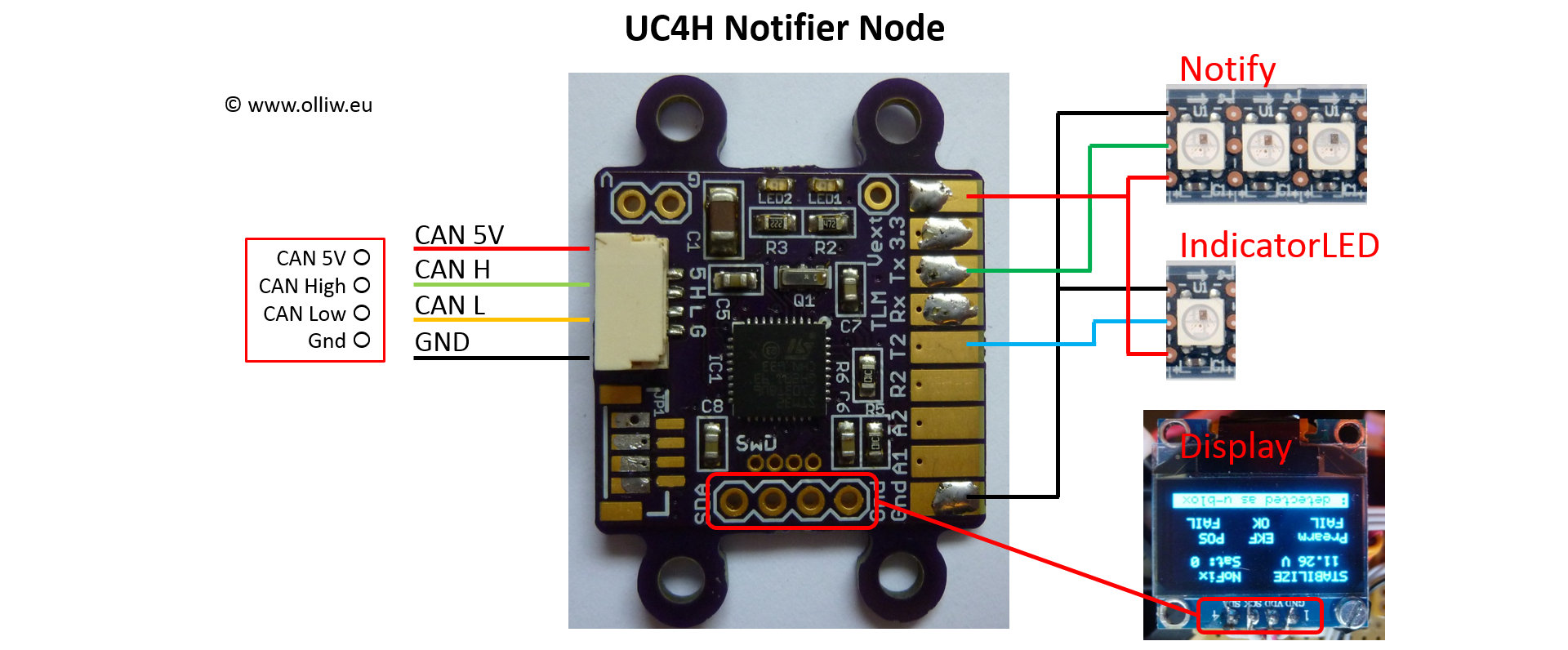
Hardware-wise the UC4H Notifiers can come in many flavors. They may come as individual boards, may come as combinations, or even as add-ons to other UC4H nodes. They can be build, as usual, using the DIY „bluepill“ approach. The best option is however to use the general-purpose UC4H node. I have e.g. realized a UC4H Notify&Display combo-node, and a UC4H OreoLEDs node using it.
The firmware for the UC4H Notify and Display node comes bundled with the UC4H IndicatorLED node.
UC4H Notify
I got a bit annoyed by the fact that ArduCopter/Pixhawk doesn’t give me the status information I’d like to see before take-off. For instance, since using ArduCopter 3.6 I often experience that I can’t switch to PosHold in the first few minutes after take-off, which is because some things have not yet settled. This information, that the GPS-assisted modes are usable, is even not displayed in ground control stations, so that a user just can’t know. One purpose of the UC4H Notify node is to make this information easily available via LEDs. The node has LEDs to signal the
- GPS status (red: no fix, yellow: 2D fix, green: 3D fix)
- EKF and POS status (red: EKF bad, yellow: EKF OK but no POS, green: POS OK)
- pre-arm checks (red: checks failed, green: checks passed)
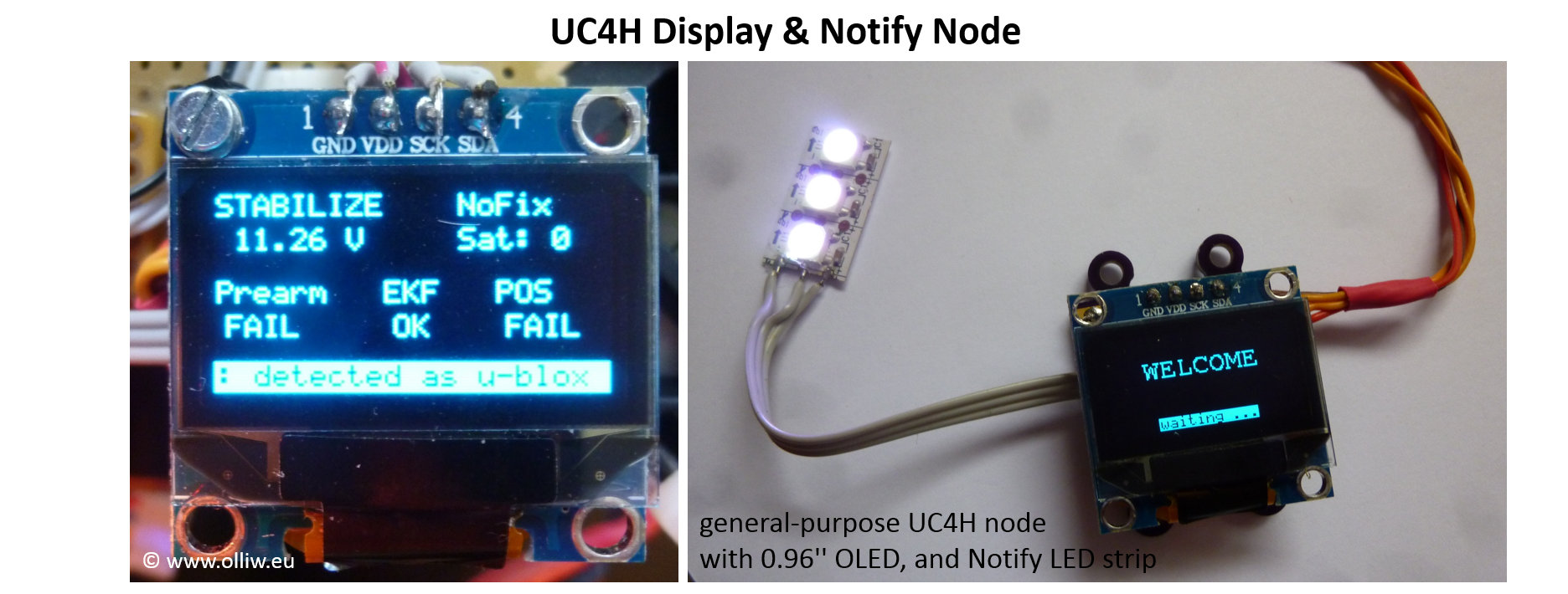
UC4H Display
Much more detailed information about the vehicle’s condition is provided by the UC4H Display node. It is similar to ArduPilot’s Onboard Display in intention, but is per UAVCAN and not I2C, offers more information, and has additional functionality possibile only thanks to its own microcontroller. For instance, it supports up to four different screens and can be user configured by uploading a simple text file. The display comes in very handy when one isn’t using a ground control station. One however needs to be close to read it off. It is thus not a substitute for e.g. the UC4H OreoLEDs, but is a great addition.
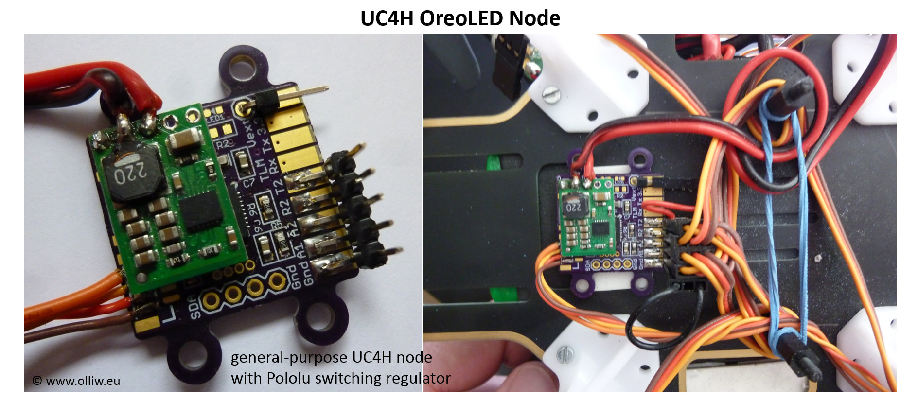
UC4H OreoLEDs
The UC4H OreoLED node adds lightning to the vehicle. It is inspired by, and in fact closely mimics, the lightning of the 3DR Solo. So, the colors and blinking sequences provide some indication of the status during startup and in flight (see e.g. here). In some sense the OreoLED node is the most useful node among the UC4H notifiers. That is, if I would have to choose when I could have only one of them, I would definitely go with the OreoLEDs.
Builds
As always, also these nodes can be build using the DIY approach mentioned repeatedly on this page. The general-purpose UC4H node however provides the best option, but also the UC4H ESC Mini PCB can come in handy too; both give small and convenient nodes. The LEDs are made of standard WS2812 LED strips, cut down to the desired number of LEDs. For the UC4H Notify node this would be three LEDs. For the OreoLED and IndicatorLED nodes it can be up to 10 on each channel. E.g., I use 5 LEDs per arm for the OreoLEDs. The display for the UC4H Display node is a standard 0.96“ OLED display (get one with the pin sequence GND-VCC-SCK-SDA).
The power supply needs some attention. The power consumption of the three LEDs for the UC4H Notify node is in the 100 mA range, which normally should be no problem, but can overload the available power on the 5 V CAN bus line. Since the UC4H Notify node is not operation critical, I power it directly from the 5.3 V source of the UC4H PowerBrick, and not through the 5 V CAN bus output of the flight controller. For the OreoLEDs the power consumption is even more critical; in my case 20 LEDs (five on each arm) need to be powered. Thus, here I have added a separate 5 V switching regulator directly powered by the battery (connected of course after the UC4H PowerBrick). They can also be powered from the 5.3 V, of course, if that source has enough ‚juice‘. The general-purpose UC4H node is prepared for both methods, and makes using them most easy.
Documentation
A detailed disussion of the UC4H Display and Notify nodes can be found in the left video. The right video present the user configuration feature of the UC4H Display node. The UC4H IndicatorLEDs and OreoLEDs were discussed before in above chapters.
These chapters may also be of interest:
* Build Information
* Supported UAVCAN Messages
UC4H IndicatorLED
The UC4H IndicatorLED node also reports back some information about the status of the ArduPilot flight controller, like the UC4H Notifier nodes. However, in contrast, it listens to the uavcan.equipment.indication.LightsCommand standard data type, which is emitted by ArduPilot (with light_id = 0). It works like any other RGB LED which ArduPilot uses as indicator LED.
The UC4H IndicatorLED node actually doesn’t come stand alone, i.e., there is no dedicated firmware for it. Instead it is bundled with other nodes, that is it is integrated into the UC4H GPS-Magnetometer-Barometer and the UC4H Notify and Display nodes.
This allows supercool builds, such as a GPS and magnetometer unit, which also has LED indicator lights.
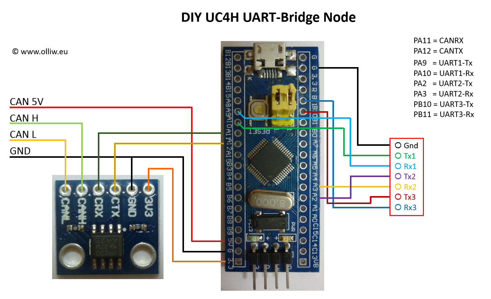
UC4H UartBridge Node
The UC4H UartBridge node allows one to connect any device with a standard UART/serial port, such as a GPS module or TFMini range finder, and to communicate with it through the CAN/UAVCAN bus. It’s like a USB-TTL adapter, except that the USB frontend is now UAVCAN. The UC4H UartBridge node provides up to three UART ports (two on boards using the STM32F103T8 chip such as the general-purpose UC4H node, and three on boards using the STM32F103C8/CB chip such as the bluepill).
This is supercool; these videos should explain it all:
Builds
As usual, the general-purpose UC4H node can be used, as well as the DIY bluepill approach.

Documentation
The UC4H UartBridge is really most easy to use. The key addition to any normal UART port is the parameter ChannelId, which needs to be set to equal values on both sides of the communication path (-1 means disabled). Typically the two sides would be a UC4H UartBridge and a Pixhawk (running BetaCopter). In this case the UART baudrate has to be set only on the Pixhawk side, as you would do it with any normal SERIAL port, but not also on the UC4H UartBridge; the baudrate of the UC4H UartBridge will be set automatically to the baudrate used by the Pixhawk. Please watch the two videos in the above for further explaination.
A screenshot of the parameters of the node can be found here:
* https://github.com/olliw42/uavcan4hobbyists/tree/master/firmware%20binaries/parameter-screenshoots
These chapters may also be of interest:
* Build Information
* Supported UAVCAN Messages
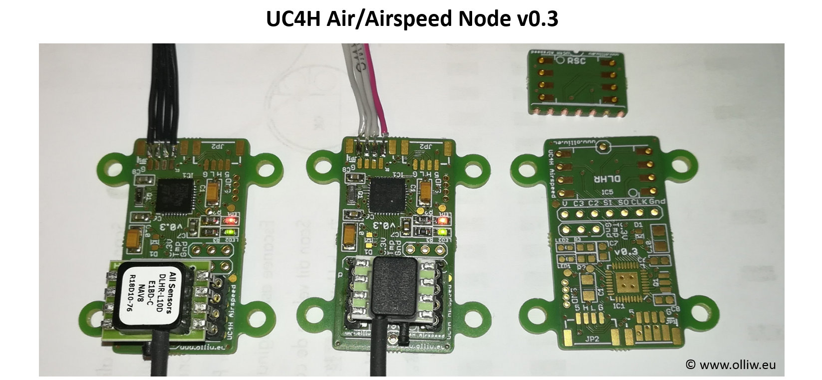
UC4H Airspeed-AngleOfAttack Node
The UC4H Airspeed-AoA node is designed to be multifunctional and measure the differential pressure of a pitot-static tube, static pressure, air temperature and angle-of-attack. It currently can be equipped with the DLHR differential pressure sensors from AllSensors, or the RSC TruStability pressure sensors from Honeywell. From the data sheets both are supposed to provide top-notch performance.
This node is described in more detail in a separate article, where also background is given: UC4H Airspeed Node.
The firmware currently allows us to measure differential pressure or airspeed, respectively, and air temperature. The node has successfully passed flight tests (see here), and a PCB design has been released (see here). The results are very promising. For instance, for a RSC ±20 inH2O sensor the orientational dependence is only 0.5 Pa, which can be compared to the 8 Pa of the MS5525DSO sensor. Also, the zero offset appears to be well below ±1 Pa, after auto zeroing and offset correction. Further test results, also comparing the DLHR and RSC sensors, are reported here. Bench and practical testing of the node is still ongoing, in order to figure out, e.g., which one is better, the DLHR or the RSC differential pressure senor.
The UC4H Airspeed-AoA node also offers the possibility to connect a magnetic rotary encoder (currently the AS5048A is supported). This allows us to build an angle-of-attack sensor (of the vane type, see here), which should be considered crucial for flight safety.
The UC4H Airspeed-AoA node is developed in cooperation with Evan, who especially contributes the in-flight testing. Thanks so much, Evan!
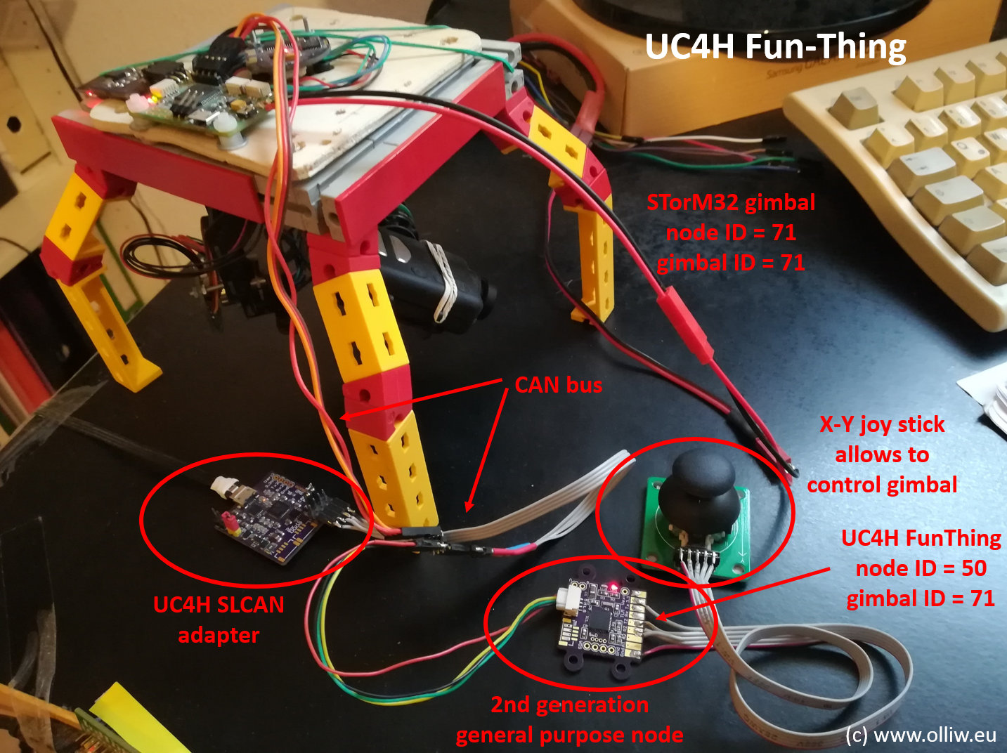
UC4H FunThing
The UC4H FunThing node doesn’t really serve a purpose in the sense that you ever would install it on your vehicle. Its main use is to have a thing to play with when you’re starting to get into the UAVCAN world. It can also be used for some level of testing or developping.
In more detail: The UC4H FunThing node allows you to connect two potentiometers and a button, and to configure it to emit various UAVCAN messages those fields are filled with values derived from the ADC readings of the potis and the button state.
The node supports emitting a large number of messages, which includes the ESC, actuator, magnetometer, barometer, airspeed, battery and tunnel messages, as well as the UC4H-specific GenericBatteryInfo and STorM32 gimbal UAVCAN messages. For the complete list check out the chapter Supported UAVCAN Messages: UC4H FunThing. So, by connecting the UC4H FunThing you can observe these messages using a SLCAN adapter and the UAVCAN GUI Tool, and e.g. plot their field value. You also can use the UC4H FunThing to actually control things such as two ESCs, two servos, or a STorM32 gimbal by UAVCAN, to name some examples. Obviously, for controlling ESCs or servos, the UC4H Esc-Actuator node would be a natural counterpart.
Builds
As always, also this node can be build using the DIY approach. The firmware is however targeted at the general-purpose UC4H node, which thus provides the best option.
UC4H MAVLinkBridge
The UC4H MAVLinkBridge is not a UAVCAN node, and thus unlike the other devices in the above. It’s purpose is to establish a path of communication between uart-like serial MAVLink channels and the UAVCAN nodes on the CAN bus. This allows us, for instance, to configure the UAVCAN nodes using standard tools, such as the ground control station MissionPlanner.
The UC4H MAVLinkBridge’s current primary function is to implement the UAVCAN Interaction protocol, i.e., to „enable the user to configure, monitor, and control the on-board UAVCAN nodes via the existing MAVLink connection“, to cite from there. This is indeed working great now, and makes any follow up configuration of the UAVCAN nodes so much more convenient.
As usual, the UC4H MAVLinkBridge can be build with the DIY approach, but also using a general-purpose UC4H node.
UC4H Bootloader
The UC4H Bootloader is a piece of code and not a physical node. It is however a much needed improvement to the UC4H suite from a user perspective, as it provides us with a user-friendly firmware upgrade of the UC4H nodes using e.g. Pavel’s great UAVCAN GUI Tool.
Given the fact that the firmwares for the UC4H nodes get constantly improved and that upgrading a node using e.g. the SWD/ST-Link approach can be a pain once the node is installed in the vehicle, a more user-friendly method is clearly highly desirable. This is especially true with the many nodes of a fully UC4H-ized copter. Bootloaders were invented exactly for this, and the UC4H Bootloader follows the established paths. Developing a UAVCAN bootloader is however a bit special since the UAVCAN concept and protocol provides some additional challenges not encountered in „usual“ bootloaders. Also, the tools are not fully fletched out and workarounds had to be found. Anyway, finally, the UC4H Bootloader came to live and is now available for everyone’s use.
Documentation
First the UC4H Bootloader needs to be flashed into the microcontroller of the UC4H node. This is done in exactly the same way as you would normally flash firmware, i.e., by using a ST-Link and the SWD pins or a USB-TLL adapter and the system bootloader on the UART1 pins. When doing this it is recommended to also do a full erase of the flash memory.
Once the UC4H Bootloader is flashed, the firmware of the UC4H node can be upgraded using e.g. the UAVCAN GUI Tool. It is not super-convenient for this purpose (and slightly buggy), but is sufficiently convenient to be useful. Attention needs to be paid to which firmware is flashed: The UC4H Bootlader enabled firmwares have a „-4bl“ in their name; the regular firmwares won’t work (but don’t worry, it won’t crash the bootloading capability).
When the node is in the bootloader it behaves somewhat differently to when the main application is running; this is summarized in this table:
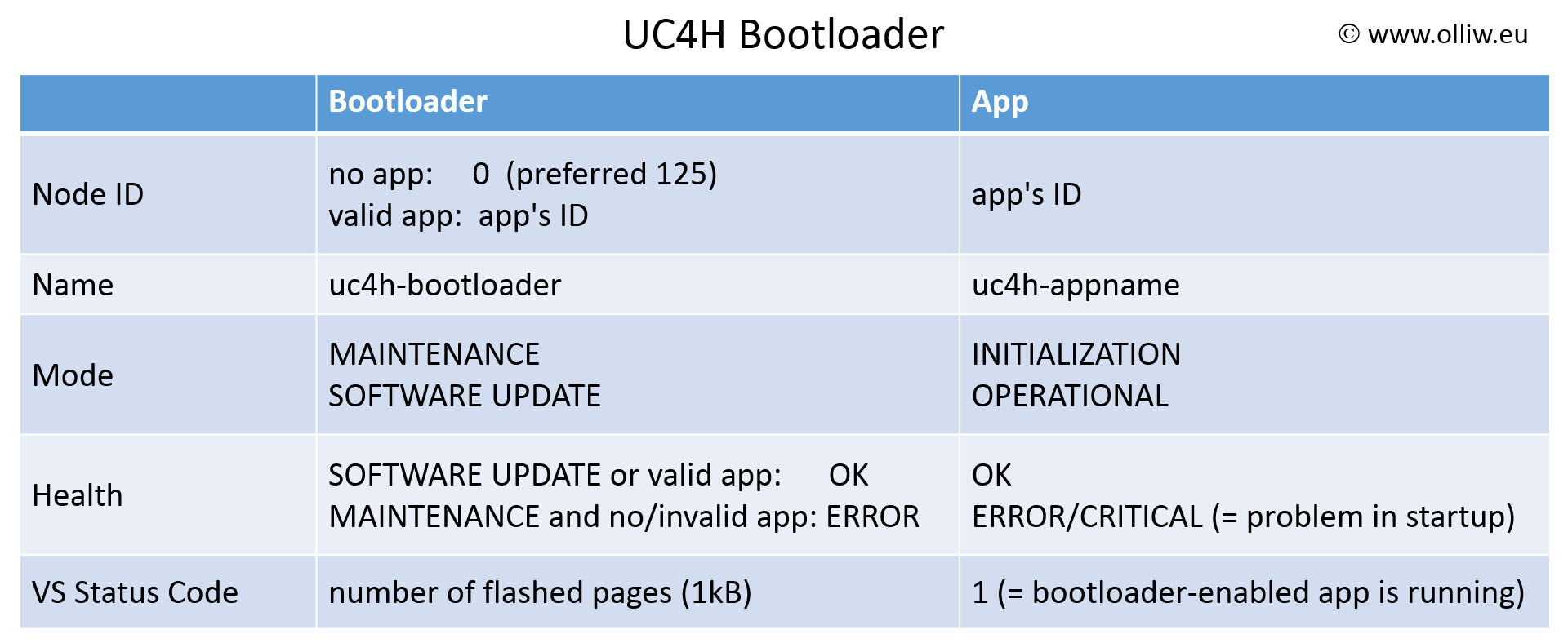
Lastly, it probably should be mentioned that the UC4H Bootloader is not a general-purpose UAVCAN bootloader. For instance, it wouldn’t work with non-UC4H firmwares. This is so because of the somewhat unique needs for UC4H nodes.
UC4H SLCAN Adapter
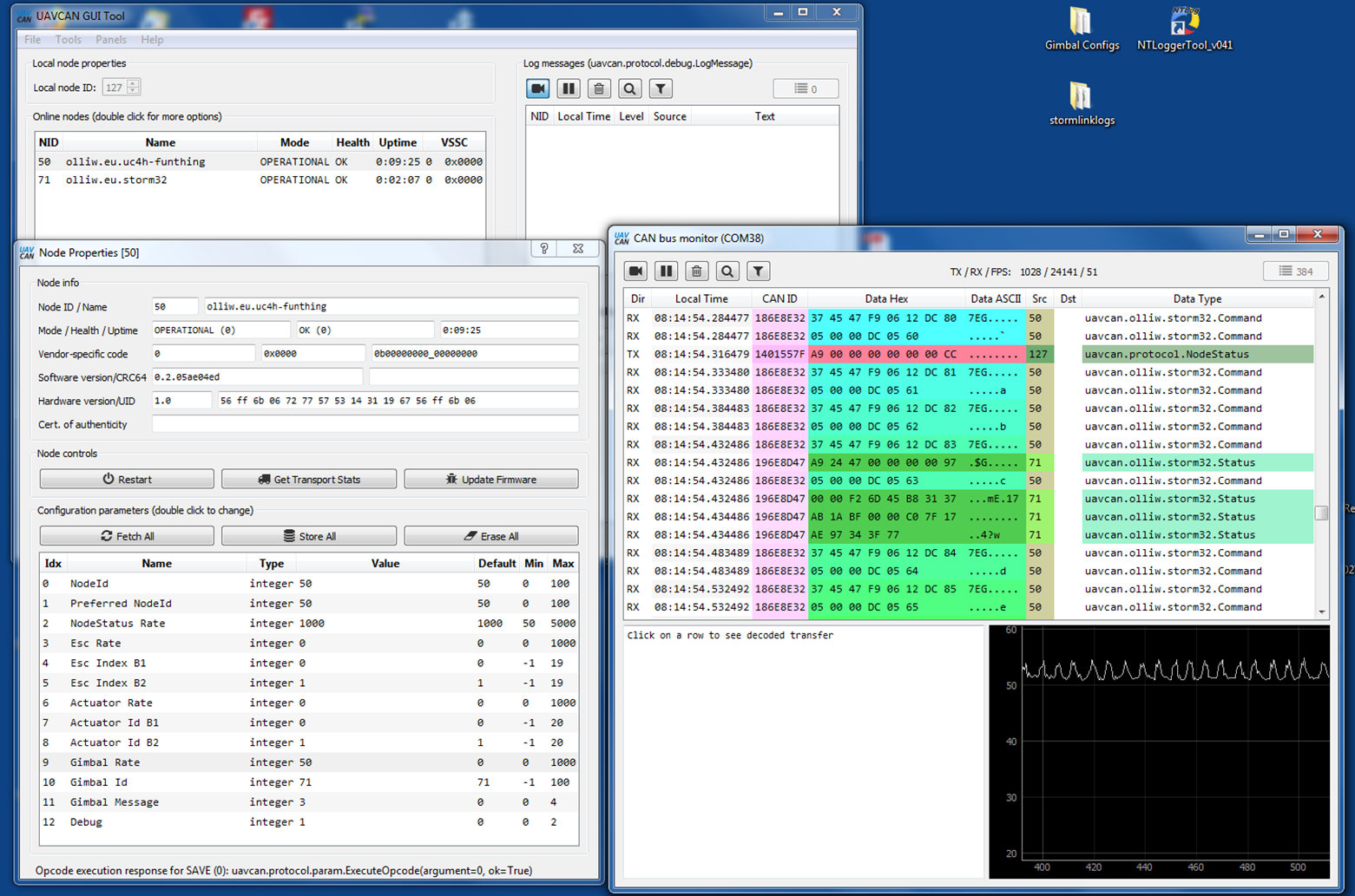
The SLCAN adapter is an indispensable tool for checking and debugging the proper functioning of a UAVCAN network. Currently it is also absolutely required for setting the node parameters, since ArduPilot doesn’t offer any such means.
In simple terms, it is a USB-CAN adapter, which is connected to the CAN bus on the one side and via USB to a PC on the other side. On the PC side the UAVCAN GUI Tool, which is freely available as part of the UAVCAN project, provides a nice software for doing a lot of things, such as spying the messages on the CAN bus, plotting data, setting node parameters, and so on (all credits to Pavel!).
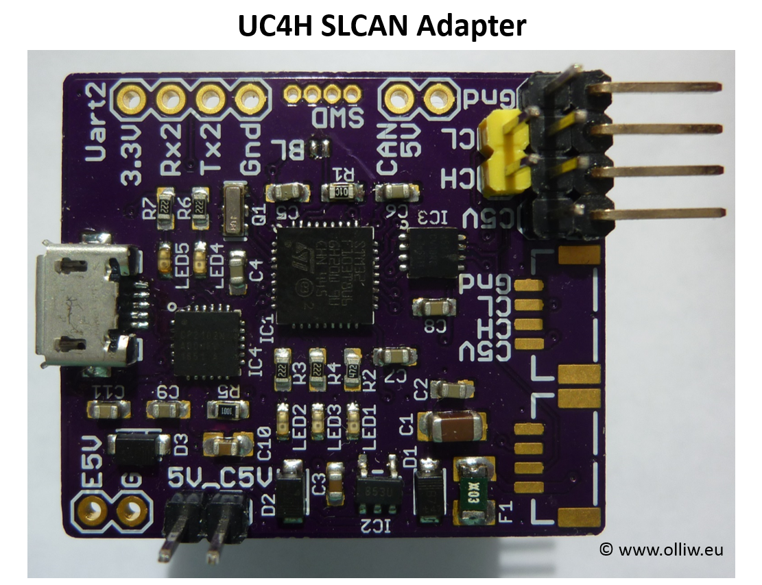
Builds
Within the UC4H project, the SLCAN adapter can be build in two ways. Firstly, I’ve designed a simple PCB board, which is relatively compact, and quite handy. It also allows one to select different powering schemes for the CAN bus, and provides the fuse & diode protection in accordance with the standard.
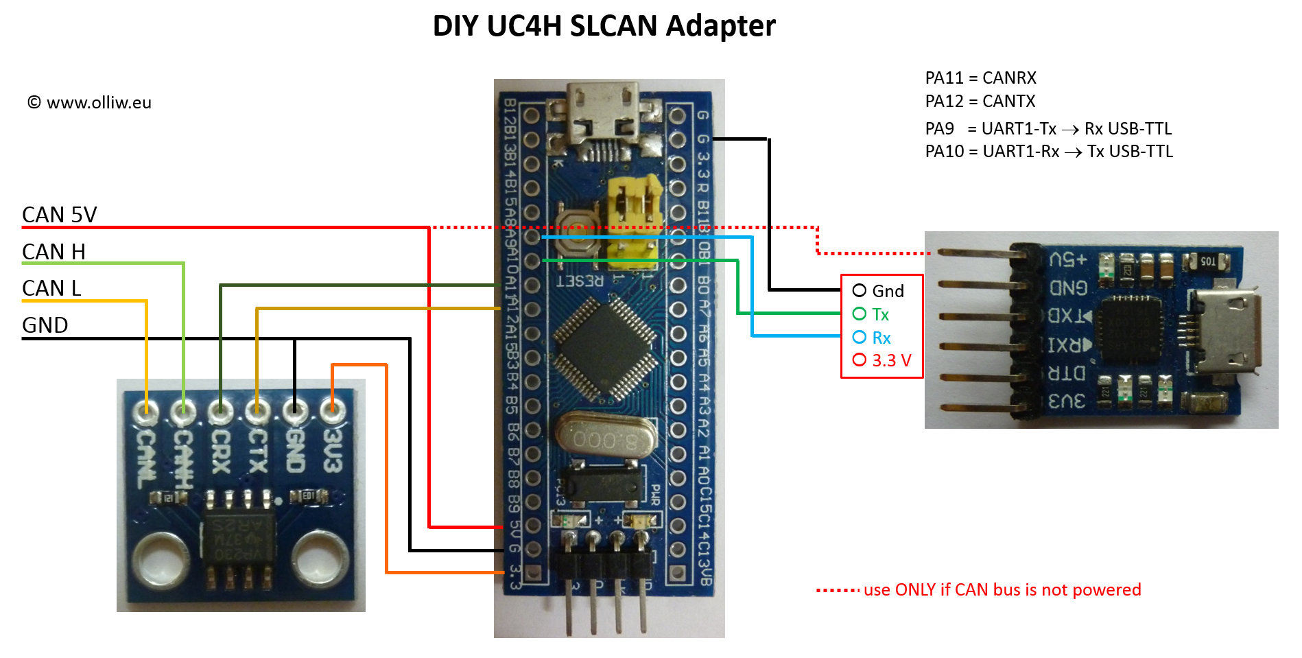
Alternatively, as usual, the UC4H SLCAN adapter can be build using cheaply available standard components. For instance, in addition to the bluepill and CAN transceiver module mentioned in the above, at $1.80 and $1.89, I bought this USB-TTL adapter at $1.02. Total cost: $4.71. That’s very acceptable, isn’t it? 🙂 The connection scheme is:
Documentation
Please consult also the chapter Build Information.
UC4H Cube Carrier
The UC4H Cube Carrier is a carrier board for the Pixhawk Cube, which is small, cheap, and yet fully functional. It is designed towards using CAN bus as the main communication backbone between the flight controller and the pheripherals, such as GPS, magnetometer, ESCs, and so on. It in fact allows us to build a „CAN-only“ vehicle. It furthermore pays attention to proper power schemes for thr CAN bus, and provides a voltage measurement of the CAN bus 5 V line.
The concept and details are disucssed also in this two videos:
Build Information, more Details
Building the UC4H nodes is not very difficult. This chapter aims at collecting some useful info.
Build Reports
- Great build report of a DIY UC4H SLCAN adapter and GSP/mag node by rcgroups user ThonTillman, here.
- Build report of a DIY ESC-Actuator node by rcgroups user mike_kelly, here and posts before.
Useful info for setting up and using the node can be found in the great blogs by Mike:
Please note that given the date of the blogs some information might be outdated.
Node Parameters
Screenshots of the parameter list can be found for each node in the UC4H github repo:
https://github.com/olliw42/uavcan4hobbyists/tree/master/firmware%20binaries/parameter-screenshoots
Bootloader
Note that the bootloader’s Node ID is 0 by default. That is, the dynamic node id allocation server in the UAVCAN GUI Tool must be activated in order for the node to show up! It is generally recommended to always enable the dynamic node id allocation server. Without it the UAVCAN GUI Tool is not always reflecting what’s going on on the CAN bus, which sometimes can be quite confusing.
This should never happen, but in case the bootloader should get stuck and doesn’t start up anymore, when it can be forced by connecting either the SWD-CLK or SWD-IO pin to GND (not both) during power up.
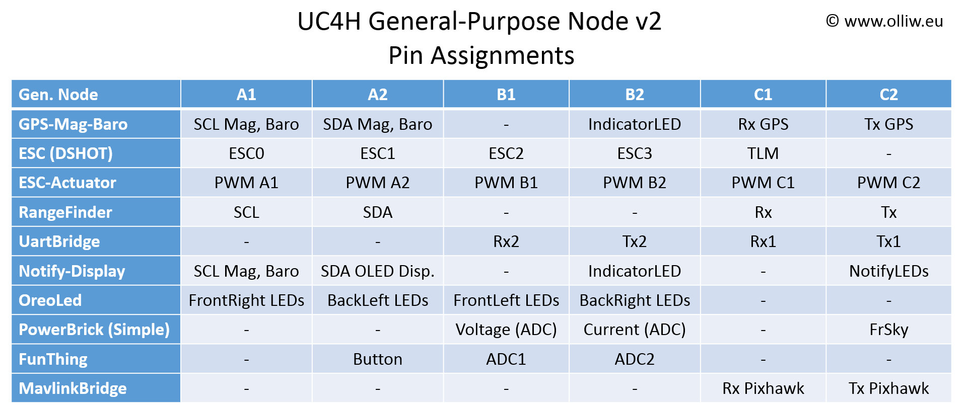
General-Purpose UC4H Board v2
The usage of the pins of the General-Purpose UC4H Board v2 by the various firmwares is as follows:
GPS Mag Baro Node
For the GPS it is highly recommended that the UAVCAN tunnel is used (Uart1 ChannelId >= 0), and not the UAVCAN uavcan.equipment.gnss.Fix message (the tunnel requires BetaCopter). Using the latter works fine (I flew with it for a year or so 😉 ), but it is somewhat clumsy. I stopped developing it further once I saw that the UAVCAN tunnel message is comings. Its (only) advantage is compatibility with current ArduPilot. If it shall be used, please note: The GPS needs to be configured to 115200 bps by hand (57600 bps for firmwares v0.26 and before), using e.g. the ublox software tool. Description of how to do that can be found in e.g. the old rcgroups discussion thread.
UAVCAN GUI Tool
In order to be able to decode the UAVCAN messages on the CAN bus, this tool must know about the definitions of the UAVCAN messages. The UC4H-specific uavcan.olliw.uc4h.GenericBatteryInfo, uavcan.olliw.uc4h.Notify, and uavcan.olliw.uc4h.Distance messages used by the UC4H PowerBrick, UC4H Notifier, and UC4H RangeFinder nodes, as well as the STorM32 UAVCAN messages, are not part of the standard set. They thus need to be made aware to the tool by copying the message definition files to a particular folder: Move the folder „olliw“ and it’s subfolders with the .uavcan dsdl definition files to the folder „C:\Program Files (x86)\UAVCAN\UAVCAN GUI Tool\uavcan\dsdl_files\uavcan\“. Now, after a restart, the UAVCAN GUI tool should show the new messages in e.g. the bus monitor, and not display „unknown“.
DIY Builds
Note that the connection schemes for the DIY builds shown in the above are for the suggested CAN transceiver module. They may be, and mostly likely will be, different for other CAN transceiver modules, see e.g. here and here and here.
It has been reported by several users that the cheap SN65HVD230 CAN transceiver modules suggested in the above can have varying quality. Better buy some spares.
DIY SLCAN Adapter
USB-TTL adapters often use the CP2102 chip, like the one suggested in the above. The SLCAN firmware works with a baud rate of 1000000 bps, which the CP2102 does not handle by default. It must be configured to it. The procedure is however simple, see here. Note: This does not apply to the newer CP2102N chips, as they are used e.g. on the UC4H SLCAN adapter PCB; these do handle 1000000 bps out of the box.
Power Brick
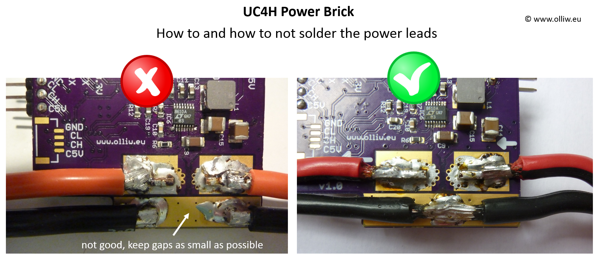
It is important to solder the battery wires appropriately to the module; the PCB traces shall not carry high currents. This figure may help:
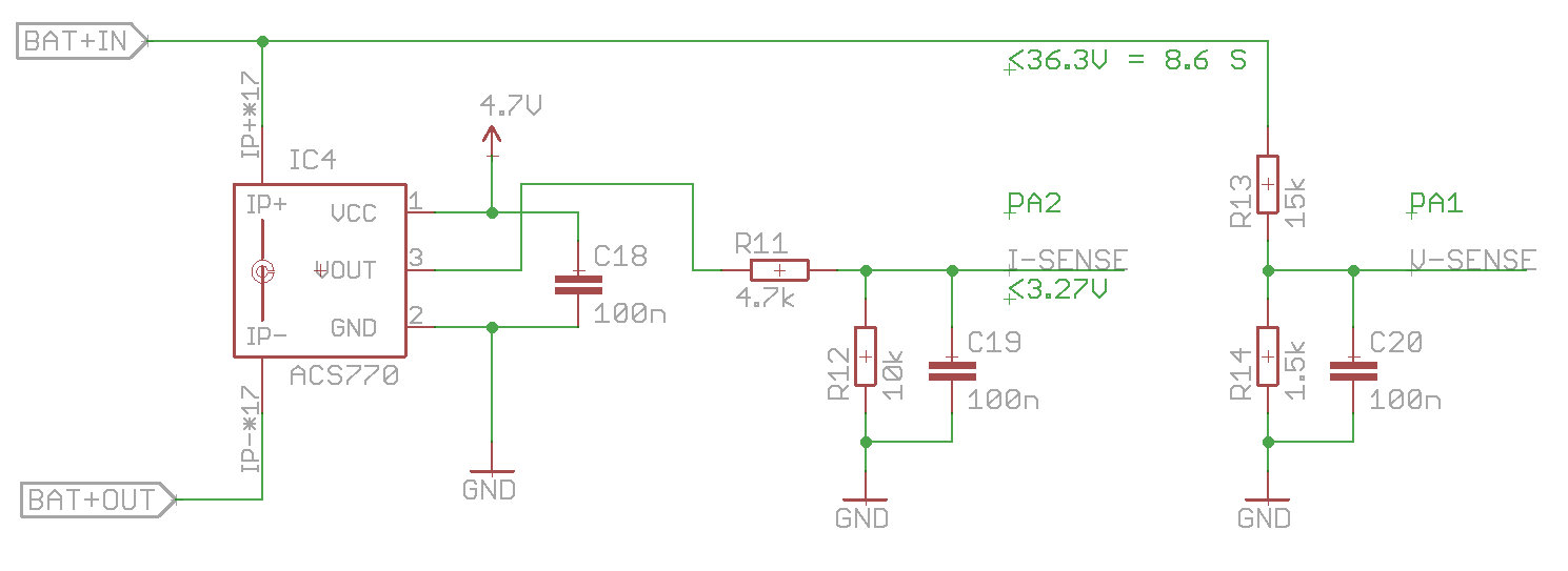
The UC4H PowerBrick can also be build following the DIY approach, which is however more cumbersome, and no suggestion is made here. The voltage and current measurement stage assumes this scheme:
UC4H Vendor Partner Program
Downloads
Go to the Github repository: github repository.
Supported UAVCAN Messages
The UC4H nodes support a variety of UAVCAN DSDL data types, which are listed in the following. Each node configures its hardware CAN filters to those DSDL messages, which it is listening to, i.e., all other received messages are rejected at the hardware level.
Messages supported by all UC4H Nodes
- uavcan.protocol.GetNodeInfo
- uavcan.protocol.NodeStatus
- uavcan.protocol.RestartNode
- uavcan.protocol.debug.LogMessage
- uavcan.protocol.dynamic_node_id.Allocation
- uavcan.protocol.file.BeginFirmwareUpdate
- uavcan.protocol.file.Read
- uavcan.protocol.param.ExecuteOpcode
- uavcan.protocol.param.GetSet
UC4H GPS-Magnetometer-Barometer
- uavcan.equipment.gnss.Fix
- uavcan.equipment.gnss.Auxiliary
- uavcan.tunnel.Broadcast
- uavcan.equipment.ahrs.MagneticFieldStrength2
- uavcan.equipment.air_data.StaticPressure
- uavcan.equipment.air_data.StaticTemperature
- uavcan.equipment.indication.LightsCommand
UC4H PowerBrick
UC4H ESC-Actuator
UC4H RangeFinder
UC4H Notifiers: Notify, Display, OreoLEDs
UC4H UartBridge
UC4H Airspeed-AoA
- uavcan.equipment.air_data.RawAirData
- uavcan.equipment.air_data.StaticTemperature
- uavcan.equipment.air_data.AngleOfAttack
UC4H FunThing
- uavcan.equipment.esc.RawCommand
- uavcan.equipment.actuator.ArrayCommand
- uavcan.equipment.ahrs.MagneticFieldStrength2
- uavcan.equipment.power.BatteryInfo
- uavcan.equipment.power.CircuitStatus
- uavcan.equipment.air_data.RawAirData
- uavcan.equipment.air_data.StaticPressure
- uavcan.equipment.air_data.StaticTemperature
- uavcan.equipment.indication.LightsCommand
- uavcan.tunnel.Broadcast
- uavcan.olliw.uc4h.GenericBatteryInfo
- uavcan.olliw.storm32.Command
- uavcan.olliw.storm32.Control