Pins and Connectors: Difference between revisions
No edit summary |
|||
| Line 1: | Line 1: | ||
__TOC__ | __TOC__ | ||
== STorM32 v2.x Boards == | |||
The STorM32 v2.4 main board provides two types of NT bus ports, the NT and NT-X ports, which in addition are also different from the NT bus connectors found on the NT modules in as much as they have swapped Rx, Tx pins. | |||
{{COMMENT|The Rx, Tx pins on the STorM32 board must be connected to the Tx, Rx pins on the NT modules.}} | |||
== STorM32 v1.x Boards == | == STorM32 v1.x Boards == | ||
| Line 5: | Line 11: | ||
On the STorM32 v1.x main boards, the I2C plug is used as NT bus connector, with the pin assignments as shown below. | On the STorM32 v1.x main boards, the I2C plug is used as NT bus connector, with the pin assignments as shown below. | ||
{{COMMENT|The Rx and Tx pins on the STorM32 board must be connected to the Tx and Rx pins on the NT modules, see also the diagram in [[What_is_STorM32_NT_about%3F|What is STorM32 NT about?]]}} | {{COMMENT|The Rx and Tx pins on the STorM32 board must be connected to the Tx and Rx pins on the NT modules. This needs a "crossing" of the Rx, Tx lines for the v1.x boards, see also the diagram in [[What_is_STorM32_NT_about%3F|What is STorM32 NT about?]]}} | ||
{{COMMENT|If starting from a "classic" (non-NT) STorM32 gimbal kit with an I2C IMU module, it is usually necessary to rewire existing cables to match the pinout of the NT bus.}} | {{COMMENT|If starting from a "classic" (non-NT) STorM32 gimbal kit with an I2C IMU module, it is usually necessary to rewire existing cables to match the pinout of the NT bus.}} | ||
Revision as of 15:15, 13 January 2017
STorM32 v2.x Boards
The STorM32 v2.4 main board provides two types of NT bus ports, the NT and NT-X ports, which in addition are also different from the NT bus connectors found on the NT modules in as much as they have swapped Rx, Tx pins.
Comment: The Rx, Tx pins on the STorM32 board must be connected to the Tx, Rx pins on the NT modules.
STorM32 v1.x Boards
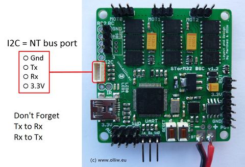
On the STorM32 v1.x main boards, the I2C plug is used as NT bus connector, with the pin assignments as shown below.
Comment: The Rx and Tx pins on the STorM32 board must be connected to the Tx and Rx pins on the NT modules. This needs a "crossing" of the Rx, Tx lines for the v1.x boards, see also the diagram in What is STorM32 NT about?
Comment: If starting from a "classic" (non-NT) STorM32 gimbal kit with an I2C IMU module, it is usually necessary to rewire existing cables to match the pinout of the NT bus.
NT v1.x Modules
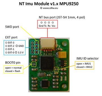
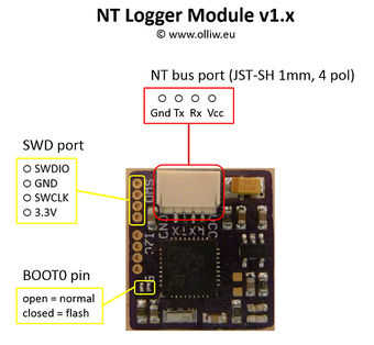
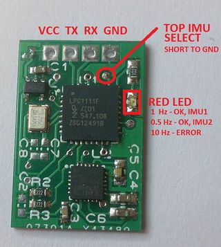
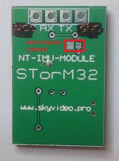
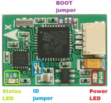
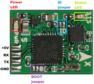
All NT v1.x modules have a 4 pin JST plug for the NT bus connector, with the pin assignments as shown below. They in addition offer a BOOT0 solder jumper, to allow for a first-time flashing. Some modules offer some further solder jumper for configuring them, some others expose also the SWD pins, and yet some others may provide access to additional extension pins.
CC3D Atom
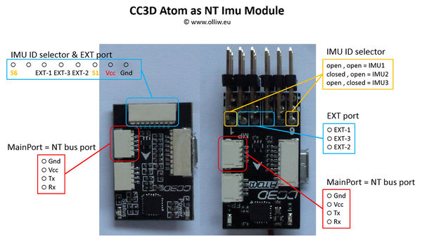
On the CC3D Atom boards the Main Port plug is used as NT bus connector, with the pin assignments as shown below. Further information on the CC3D Atom can be found here.
Comment: To close the IMU ID selector, connect the indicated pin to GND.
ENSYS NT Imu Module
These modules are available from Ensys. For further information and the vendor's page please see Ensys NT Modules.
midimon's NT Imu Module
These modules are derived from the Mini NT IMU v1.x with MPU9250. For further information please see midimon's NT IMU Module.
