3.3 V Fix Mod for STorM32 v1.31 Boards: Difference between revisions
No edit summary |
No edit summary |
||
| Line 1: | Line 1: | ||
The STorM32 v1.31 boards, which are distinguished by their on-board switching regulator, unfortunately provide a very weak 3.3 V power supply, which makes it problematic to use NT modules. Therefore, usually extra BECs need to be used with these boards. | The STorM32 v1.31 boards, which are distinguished by their on-board switching regulator, unfortunately provide a very weak 3.3 V power supply, which makes it problematic to use NT modules. Therefore, usually extra BECs need to be used with these boards. | ||
Rcgroups | Rcgroups users ckambiselis and fs008 have suggested relatively simple mods to fix that issue. | ||
== fs008 mod == | |||
For the original posts see [[https://www.rcgroups.com/forums/showpost.php?p=38547543&postcount=1842 here]] and [[https://www.rcgroups.com/forums/showpost.php?p=38567530&postcount=1897 here]]. | |||
It consists of three steps: | |||
(1) Cutting the PCB trace to the VCC pin of port I2C#1. | |||
(2) Soldering a wire from the 5 V output of the on-boards switching regulator to this pin. | |||
== ckambiselis mod == | |||
For the original post see [[https://www.rcgroups.com/forums/showpost.php?p=37897325&postcount=9994 here]]. | |||
It consists of three steps: | It consists of three steps: | ||
Revision as of 17:39, 3 November 2017
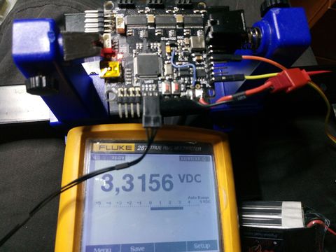
The STorM32 v1.31 boards, which are distinguished by their on-board switching regulator, unfortunately provide a very weak 3.3 V power supply, which makes it problematic to use NT modules. Therefore, usually extra BECs need to be used with these boards.
Rcgroups users ckambiselis and fs008 have suggested relatively simple mods to fix that issue.
fs008 mod
For the original posts see [here] and [here].
It consists of three steps:
(1) Cutting the PCB trace to the VCC pin of port I2C#1.
(2) Soldering a wire from the 5 V output of the on-boards switching regulator to this pin.
ckambiselis mod
For the original post see [here].
It consists of three steps:
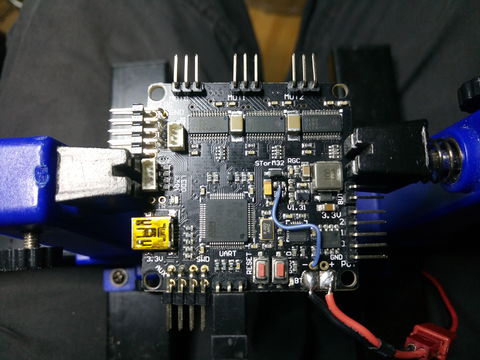
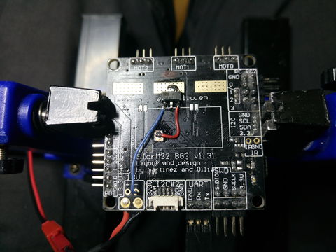
(1) Removal (desoldering) of the 3.3 V LDO regulator from board.
(2) Soldering of a stronger 3.3 V LDO regulator to the bottom of the board.
(3) Soldering of two wires to establish the connections.


