What is STorM32 NT about?: Difference between revisions
No edit summary |
No edit summary |
||
| (37 intermediate revisions by the same user not shown) | |||
| Line 1: | Line 1: | ||
One of the major drawbacks of the "old" STorM32 is the reliance on the I2C bus for communicating with the IMU(s), because of | One of the major drawbacks of the "old" STorM32 is the reliance on the I2C bus for communicating with the IMU(s), because of the sensitivity of I2C to disturbances from e.g. the motor signal wires (see the [[I2C Error Compendium]]). The STorM32 NT provides an ultimate solution by replacing the I2C bus with the NT bus, which hardware-wise is nothing else than just a standard serial UART, but using a quite high baudrate (NT stands for "New Technology"). Since the UART is low impedance and push-pull the disturbance sensitivity is very much lower than for I2C, making it practically error free. Furthermore, even if a transmission error should occur, the controller has no difficulties to recover from it, unlike with I2C. | ||
The additional cool thing about the NT concept is that it | The additional cool thing about the NT concept is that it doesn't stop here. The NT bus allows us to not only connect one NT IMU module but also further modules, such as a 2nd NT IMU module, motor driver modules, a camera controller module, a data logging module, and so on. It thus provides us with a number of further advantages: | ||
* The NT modules can be daisy-chained, which can result in quite clean wiring, and helps tremendously with e.g. slip rings. | * The NT modules can be daisy-chained, which can result in quite clean wiring, and helps tremendously with e.g. slip rings. | ||
* The NT modules can be replaced easily, resulting in extraordinary flexibility in the configuration | * The NT modules can be replaced easily, resulting in extraordinary flexibility in the configuration. | ||
* The possibility | * The possibility of replacing individual NT modules may reduce costs in case of damage. | ||
* The concept simplifies integration of technological advances: If you need encoders, build | * The concept simplifies integration of technological advances: If you need encoders, then build a FOC motor driver module (this has happened! See [[What is T-STorM32 about?|T-STorM32]]). If you need a high-quality ultra-low drift IMU module, then build a high-quality ultra-low drift IMU module. If you need a CHDK camera controller, then build a CHDK camera controller. And so on. | ||
The schemes below show, for the v3.x and v1. | The schemes below show, for the v3.x, v4.x and v1.3x STorM32 boards, what could be a typical, fully NT-ized configuration. | ||
A further cool thing about the NT concept is that one can continue to use the widely and cheaply available v1.3x STorM32 boards. The NT concept is fully compatible with them! Technically this is possible because the microcontroller pins used for the I2C port in the "old" STorM32 can also be configured as UART pins, turning them into the NT bus. Even though one doesn't need a new controller board, one nevertheless needs new hardware, at minimum one NT IMU module. | |||
However, it is pointed out that all | However, it is pointed out that - if you are using a v1.3x STorM32 board - all you need to start with is only one NT IMU module to replace the "old" I2C camera IMU. All other NT modules are optional, and not using them doesn't incur restrictions in functionality. This simple rule applies: Whenever a NT module is found, it is used, and if not, then the conventional hardware is used. For instance, if a 2nd NT IMU module is not on the NT bus, then the on-board IMU is used. Similarly you can continue to use the STorM32's motor driver outputs M0, M1, and M2, and so on. | ||
{{COMMENT|The v3.x STorM32 boards require that you use NT Motor modules in addition, as they don't have motor drivers on-board. The v4.x board does have on-board motor drivers, and all you need here is also just a NT IMU module like with the v1.3x board.}} | |||
=== Example Wiring Schemes === | |||
The typical wiring scheme for a v3.x STorM32 board can look as this: | |||
:[[File:Storm32-nt-wiring-scheme-v3x-docu.jpg|none|900px|center]] | :[[File:Storm32-nt-wiring-scheme-v3x-docu.jpg|none|900px|center]] | ||
The scheme for a v4.x board would be simlar to that for a v3.x board, except that you do not need the NT motor modules when the on-board motor drivers are used. | |||
For a v1.3x STorM32 board the wiring scheme is slightly different (note the "crossing" of the Tx/Rx lines at the NT connector on the STorM32 board): | |||
:[[File:Storm32-nt-wiring-scheme-v1x docu.jpg|none| | :[[File:Storm32-nt-wiring-scheme-v1x docu.jpg|none|900px|center]] | ||
Latest revision as of 21:43, 12 February 2024
One of the major drawbacks of the "old" STorM32 is the reliance on the I2C bus for communicating with the IMU(s), because of the sensitivity of I2C to disturbances from e.g. the motor signal wires (see the I2C Error Compendium). The STorM32 NT provides an ultimate solution by replacing the I2C bus with the NT bus, which hardware-wise is nothing else than just a standard serial UART, but using a quite high baudrate (NT stands for "New Technology"). Since the UART is low impedance and push-pull the disturbance sensitivity is very much lower than for I2C, making it practically error free. Furthermore, even if a transmission error should occur, the controller has no difficulties to recover from it, unlike with I2C.
The additional cool thing about the NT concept is that it doesn't stop here. The NT bus allows us to not only connect one NT IMU module but also further modules, such as a 2nd NT IMU module, motor driver modules, a camera controller module, a data logging module, and so on. It thus provides us with a number of further advantages:
- The NT modules can be daisy-chained, which can result in quite clean wiring, and helps tremendously with e.g. slip rings.
- The NT modules can be replaced easily, resulting in extraordinary flexibility in the configuration.
- The possibility of replacing individual NT modules may reduce costs in case of damage.
- The concept simplifies integration of technological advances: If you need encoders, then build a FOC motor driver module (this has happened! See T-STorM32). If you need a high-quality ultra-low drift IMU module, then build a high-quality ultra-low drift IMU module. If you need a CHDK camera controller, then build a CHDK camera controller. And so on.
The schemes below show, for the v3.x, v4.x and v1.3x STorM32 boards, what could be a typical, fully NT-ized configuration.
A further cool thing about the NT concept is that one can continue to use the widely and cheaply available v1.3x STorM32 boards. The NT concept is fully compatible with them! Technically this is possible because the microcontroller pins used for the I2C port in the "old" STorM32 can also be configured as UART pins, turning them into the NT bus. Even though one doesn't need a new controller board, one nevertheless needs new hardware, at minimum one NT IMU module.
However, it is pointed out that - if you are using a v1.3x STorM32 board - all you need to start with is only one NT IMU module to replace the "old" I2C camera IMU. All other NT modules are optional, and not using them doesn't incur restrictions in functionality. This simple rule applies: Whenever a NT module is found, it is used, and if not, then the conventional hardware is used. For instance, if a 2nd NT IMU module is not on the NT bus, then the on-board IMU is used. Similarly you can continue to use the STorM32's motor driver outputs M0, M1, and M2, and so on.
Comment: The v3.x STorM32 boards require that you use NT Motor modules in addition, as they don't have motor drivers on-board. The v4.x board does have on-board motor drivers, and all you need here is also just a NT IMU module like with the v1.3x board.
Example Wiring Schemes
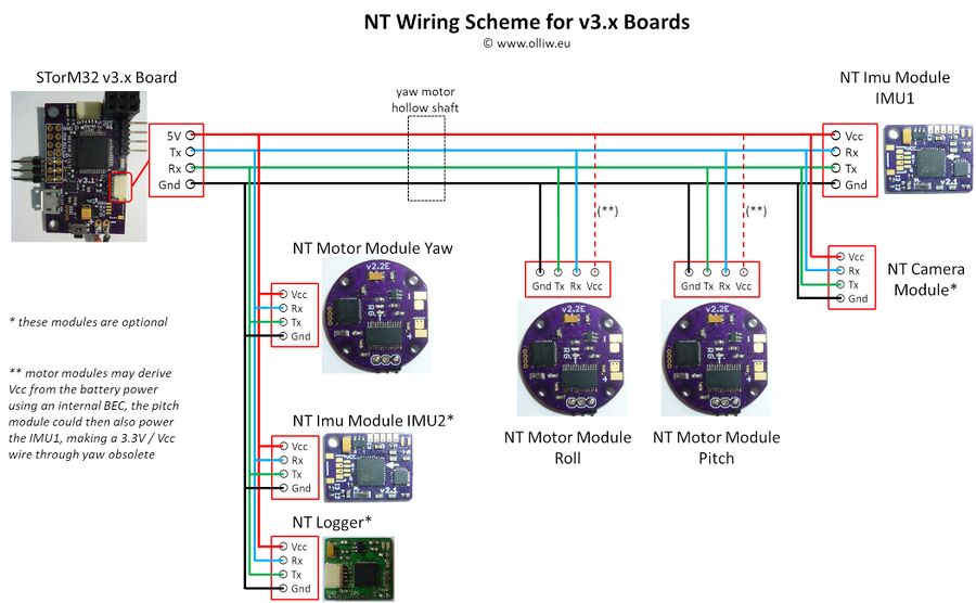
The typical wiring scheme for a v3.x STorM32 board can look as this:
The scheme for a v4.x board would be simlar to that for a v3.x board, except that you do not need the NT motor modules when the on-board motor drivers are used.
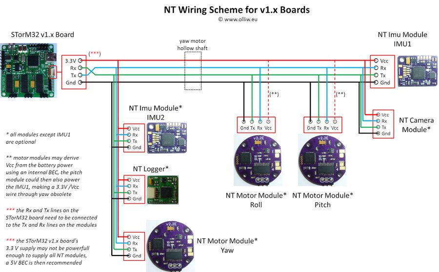
For a v1.3x STorM32 board the wiring scheme is slightly different (note the "crossing" of the Tx/Rx lines at the NT connector on the STorM32 board):

