Using STorM32 with BetaPilot: Difference between revisions
| Line 92: | Line 92: | ||
Please '''''disable''''' (set to 0) '''''all SRx''''' streaming parameters for the serial port you are using for STorM32. This avoids that the STorM32 controller is bombarded with superfluous messages and helps it to achieve consistent behavior. Depending on the vehicle type and ArduPilot firmware version you may find that the streaming parameters are enabled or disabled by default. So, please check. | Please '''''disable''''' (set to 0) '''''all SRx''''' streaming parameters for the serial port you are using for STorM32. This avoids that the STorM32 controller is bombarded with superfluous messages and helps it to achieve consistent behavior. Depending on the vehicle type and ArduPilot firmware version you may find that the streaming parameters are enabled or disabled by default. So, please check. | ||
The control of the gimbal depends also on the '''''mount mode''''' (see [[Using STorM32 with BetaPilot#Using Gimbal Protocol V2|Using Gimbal Protocol V2]]). The mount mode at startup is determined by the ArduPilot parameter [https://ardupilot.org/copter/docs/parameters.html#mnt1-deflt-mode MNT1_DEFLT_MODE]. Typical settings would be | The control of the gimbal depends also on the '''''mount mode''''' (see [[Using STorM32 with BetaPilot#Using Gimbal Protocol V2#Mount Mode|Using Gimbal Protocol V2]]). The mount mode at startup is determined by the ArduPilot parameter [https://ardupilot.org/copter/docs/parameters.html#mnt1-deflt-mode MNT1_DEFLT_MODE]. Typical settings would be | ||
* MNT1_DEFLT_MODE = 2 (MavLink Targeting) or 3 (RC Targeting) | * MNT1_DEFLT_MODE = 2 (MavLink Targeting) or 3 (RC Targeting) | ||
Revision as of 12:03, 1 March 2024
The information on this page refers to firmware v2.69e and BetaPilot (BetaCopter/BetaPlane) 4.5-dev v0.60.
The STorM32 gimbal controller can communicate with ArduPilot flight controllers via a serial UART data link using the MAVLink protocol. The serial communication allows for a much richer data transmission and accordingly richer set of features than possible with the traditional connections such as PWM, PPM, SBUS, CRSF, and alike. Examples are advanced control functions, the STorM32-Link or the NT Camera features. Furthermore, the Gimbal Protocol v2 is supported. Using the MAVLink communication can also lead to a much cleaner wiring and a more robust and reliable system.
The ArduPilot firmware is unfortunately notoriously unpleasant as regards its gimbal and camera support (flaws, not MAVLink standard conform, etc.), and thus BetaPilot was started many years ago.
BetaPilot, which includes BetaCopter and BetaPlane, is a fork of ArduPilot, with modifications which are specifically directed at the STorM32 gimbal controller. If you want to make best use of your STorM32 gimbal and want 2020-ish capabilities, then you definitely want to chose BetaPilot (BetaCopter/BetaPlane). :)
This article is about BetaPilot. For info on using the native ArduPilot firmware with STorM32, please visit the article Using STorM32 with ArduPilot.
BetaPilot
BetaPilot implements the latest MAVLink standard and in particular the STorM32 MAVLink2 mount type, which make the features below possible.
In order to establish a working communication between the STorM32 controller and the flight controller, a serial connection needs to be established, and parameters in both the flight controller and the STorM32 controller need to be adjusted, as described in the subsequent chapters.
BetaPilot is currently available for copters and planes. The code additions are however such that it should be trivial to extend to other vehicles supported by ArduPilot.
BetaPilot comes in these branches:
- BetaCopter4.3: This is based on ArduCopter 4.3.5-rc1, and is hence the go-to version for copter users. (see red message, do not use)
- BetaPlane4.3: This is based on ArduPlane 4.3.4 stable, and is hence the go-to version for plane users. (see red message, do not use)
- BetaPilot branch: This is based on ArduPilot master, which is ArduPilot's development branch (= not stable). The support of the BetaPilot branch is not steady but on and off. Typically, the BetaPilot branch is progressing when required features are in master but not in the stable or beta/rc branches, but usually it tends to lack behind, possibly even by quite a bit.
Comment: The label 'BetaPilot' is used in the following as shorthand for denoting the project or referring to BetaCopter or BetaPlane, and not to refer to the BetaPilot branch.
Firmware Binaries
For BetaCopter and BetaPlane, ready-to-use firmware binaries are provided for some few boards in the 'bp_compiled_binaries' folders:
- BetaCopter4.3.5-rc1 v057.3 binaries: link (see red message, do not use)
- BetaPlane4.3.4 stable v057.3 binaries: link (see red message, do not use)
For other boards, the respective source code needs to be compiled by the user (or you ask in the rcgroups thread to maybe help you out). For instructions on how to compile BetaCopter or BetaPlane, you just can follow the ArduPilot instructions (link); there is nothing special to do for BetaCopter/BetaPlane (except of course of cloning the correct firmware).
For installing/flashing the binary follow the common instructions for installing custom firmware. In MissionPlanner, e.g., go to 'Setup -> Install Firmware -> Load custom firmware'.
The additions by BetaCopter/BetaPlane to the main code are minimally infectious, meaning that if not used/enabled they do not impact normal behavior. It is usually no problem at all to swap the firmware between ArduCopter/ArduPlane and BetaCopter/BetaPlane, which can help sort out issues in case of doubt of the origin of an issue. The main impact of BetaCopter/BetaPlane is a slightly increased flash and RAM footprint, which can have effects on boards which are short of flash and/or RAM. That's a general problem with this kind of boards.
STorM32 MAVLink2 Mount Type
The STorM32 controller needs to be connected via one of its serial ports to one of the serial ports on the flight controller, and settings in both STorM32 and BetaPilot need to be made.
Settings in STorM32:
- Mavlink Gimbal = “Gimbal1” or higher
- Mavlink Gimbal Stream = “device status” (you also can use “mountstatus” if backwards compatibility is desired, do not use “manager status”)
- Mavlink Uart Port = “uart” if the serial port UART is used (this is the default)
- Mavlink System ID = “0” for auto-detection (which is the default) or system ID of autopilot
Other MAVLink-related settings can normally be left at their default. A complete description of the parameters is provided in MAVLink Communication: Parameters (please read it, just in case).
The STorM32 controller needs to be rebooted when you change Mavlink Uart Port. Changes to the other settings become effective immediately. However, depending on the situation, you may have to reboot the complete system (gimbal and flight controller and GCS) to reset internal states and auto-detection mechanisms in these components in order for all to work properly (so, if you change a parameter and something looks odd, restart/reset the whole system).
Settings in BetaPilot:
- MNT1_TYPE = 83
- SERIALx_PROTOCOL = 2
- SERIALx_BAUD = 115
The setting MNT1_TYPE = 83 enables the STorM32 MAVLink2 mount. SERIALx can be any of the flight controller's serial ports SERIAL1, SERIAL2, and so on ('x' stands for 1, 2, ...). The default baudrate of the STorM32 serial ports is 115200 bps, SERIALx_BAUD is hence set to 115. The flight controller must be rebooted for the changes to become effective.
With these settings you should notice that:
- In MissonPlanner or any other GCS, a MAVLink component named GIMBAL is present in addition.
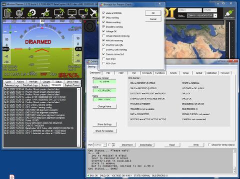
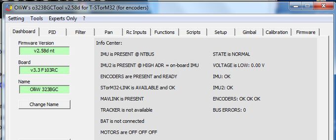
- In the STorM32 [GUI:Dashboard], the MAVLINK field shows PRESENT.
- In the STorM32 [GUI:Dashboard], the STorM32-Link field shows PRESENT or a similar positive message.
Checking these points provides a quick indicator for whether things are working or not. For further testing, please see Testing the Connection.
The above settings establish the basic configuration. Some features need additional adjustment of some parameters, which will be described in the following chapters.
Baudrate Settings
It is strongly recommended to use 230400 bps, especially if STorM32-Link is being used.
The baudrate needs to be changed in both STorM32 and BetaPilot:
- Uart Baudrate = “230400”
- SERIALx_BAUD = 230
Here it was assumed that the STorM32 controller's UART port is used for MAVLink, i.e, Mavlink Uart Port = “uart”. If this is not your case, then set the baudrate for the serial port which you are using.
Further Settings in BetaPilot to Consider
Please disable (set to 0) all SRx streaming parameters for the serial port you are using for STorM32. This avoids that the STorM32 controller is bombarded with superfluous messages and helps it to achieve consistent behavior. Depending on the vehicle type and ArduPilot firmware version you may find that the streaming parameters are enabled or disabled by default. So, please check.
The control of the gimbal depends also on the mount mode (see Using Gimbal Protocol V2). The mount mode at startup is determined by the ArduPilot parameter MNT1_DEFLT_MODE. Typical settings would be
- MNT1_DEFLT_MODE = 2 (MavLink Targeting) or 3 (RC Targeting)
For unrestricted control by the Gimbal Protocol v2 messages, the setting MNT1_DEFLT_MODE = 2 should be choosen.
Depending on the details of the ArduPilot setup it can come to DMA contention issues (has nothing to do with BetaPilot, is low-level ArduPilot behavior), which especially can make the STorM32-Link to not work properly. If you have hints that such an issue exists in your case, you can try this: Disable all unused serial ports (SERIALx_PROTOCOL = -1)(this is generally a good advice to do). You also may try enabling the TX_NoDMA flag in the SERIALx_OPTIONS parameter (and maybe also the RX_NoDMA flag). It also can help to simply use a different serial port on the flight controller (different SERIALx). Please do not hesitate to join a STorM32 discussion thread at rcgroups for further discussion. (the original thread discussing the issue is here)
BetaPilot also supports the MAVLink messages of the mLRS project, which can provide substantial benefits when mLRS is used. Consult the mLRS discussion thread for further information.
STorM32-Link
Requires this additional setting:
Settings in STorM32:
- STorM32Link Configuration = “v1” (or “yaw drift comp.” if only yaw drift compensation is desired)
With the STorM32 MAVLink2 mount enabled (MNTx_TYPE = 83), the flight controller also sends the STorM32-Link data to the STorM32 gimbal. However, these data are used by the STorM32 controller only when STorM32Link Configuration = “v1” (or “yaw drift comp.”) is also set.
Comment: This setting does not affect the information shown in the [GUI:Dashboard] STorM32-Link field! The information shown there, such as 'not available', PRESENT, AVAILABLE, OK, reflects the incoming data stream, but not its usage.
For more details on the STorM32-Link, please read the article STorM32-Link.
Virtual Channel Configuration
Requires this additional setting:
Settings in STorM32:
- Virtual Channel Configuration = “serial”
With this setting, all STorM32 functions can be invoked by selecting any of the “Virtual-1” - “Virtual-16” input channels, exactly as one would do it if the STorM32 controller would be directly connected to a receiver by traditional means (PWM, PPM, SBUS, and so on).
This allows us to do many useful things, such as to activate a script or to start/stop video recording from the transmitter. It however also allows us to do nonsense, and it is in the user's responsibility to avoid that.
For instance, if ArduPilot is in Rc Targeting mode, and e.g. Rc Pitch Control is set to a virtual input channel, then the gimbal may move in funny ways since it may receive the transmitter stick information from both ArduPilot and the receiver. On the other hand, if ArduPilot is in GPS or ROI Targeting mode, then one gets "free look", which is useful and quite cool actually. As said, all this is exactly as if the receiver would be directly connected to the STorM32 controller on its RC input ports.
Comment: BetaPilot ignores channel data which are sent to the flight controller via the RC_CHANNELS_OVERRIDE message but sends the channel data exactly as the flight controller obtains them from a receiver by the "traditional" means such as CRSF, SBUS, or PPM, or the mLRS specifc RADIO_RC_CHANNELS message. That is, it indeed works as if the receiver would be connected to the STorM32 controller.
Passthrough Configuration
This feature allows you to connect the STorM32 GUI to the USB or any (MAVLink enabled) serial port of the flight controller, and to directly communicate with the STorM32 gimbal.
This is extremely convenient for configuring the STorM32 gimbal when it is e.g. installed permanently in the vehicle. This also works via a wireless telemetry link, and thus opens the option of e.g. tuning the gimbal during flight, and further unheard of possibilities for controlling the gimbal during flight.
This preliminary demo video demonstrates the pass-through feature:
Prearm Checks
Requires this additional setting:
Settings in STorM32:
- Prearm Check != “off”
The STorM32 controller supports a rich set of prearm checks. The status of the prearm checks is passed to the flight controller, and lets it handle them exactly like it handles any of its other prearm checks. For instance, in a GCS it will display a message "PreArm: Mount: not healthy" in intervals of 30 seconds, as well as more information such as "MNT1: prearm checks FAIL: mot,volt" which provides more insight into which prearm check failed.
This provides a simple and quick check that the STorM32 gimbal is working as intended, and is obviously also highly useful to check before takeoff that the system is working normally, including the gimbal.
For more details on the prearm checks, please read the article Prearm Checks.
Auxiliary Functions
The following ArduPilot auxiliary functions can be used:
- "Mount Lock": allows to switch between yaw pan (aka follow) and yaw hold (aka lock) mode. HIGH: yaw lock, else yaw pan.
- "Retract Mount1": allows to put the gimbal into retract mode (MAV_MOUNT_MODE_RETRACT, GIMBAL_DEVICE_FLAGS_RETRACT). HIGH: retract, MID: last mode, LOW: default mode.
- "Camera Trigger": triggers taking a photo. HIGH: take photo when in photo mode.
- "Camera Mode Toggle": allows to switch between photo and video mode, as well as starts/stops the video recording. HIGH: change to video mode and start recording, MID: stop video recording if in video mode, else nothing, LOW: change to photo mode and take picture.
- "Camera Record Video": starts/stops video recording when in video mode. HIGH: start recording, else stop recording.
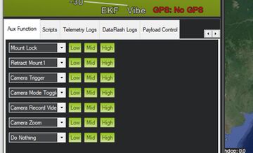
The auxiliary functions can be invoked by associating them in ArduPilot to RC channels (see ArduPilot: Auxiliary functions). They also can be invoked by sending the MAV_CMD_DO_AUX_FUNCTION command to the autopilot. The latter can be connveniently done via MissionPlanner's Aux Function tab.
Comment: The auxiliary functions "Camera Mode Toggle" and "Camera Record Video" require that the CAM_TRIGG_TYPE parameter is set to 3 (Mount).
Comment: Except of "Retract Mount1", the same functionality can also be achieved using the STorM32's functions in combination with the virtual channels feature. This approach is in fact more STorM32-ish, and offers more possibilities, like triggering scripts and more, which are not available via ArduPilot's auxiliary functions mechanism. The advantage of using ArduPilot's auxiliary functions can be that it's more ArduPilot-ish, and that you can trigger them through e.g. MissionPlanner.
Statustext Messages
With the STorM32 MAVLink2 mount enabled (MNTx_TYPE = 83), the flight controller sends various MAVLink STATUSTEXT messages to a ground control station, providing additional information.
In addition, MAVLink STATUSTEXT messages can also be send via STorM32 scripts, the SENDMAVTEXT script command specifically. This provides a very versatile mechanism to communicate to the user.
MAVLink Camera Microservice
BetaPilot implements the MAVLink protocol as specified in the MAVLink standard. Therefore, with BetaPilot installed, also the MAVLink Camera Microservice can be fully used.
The STorM32 gimbal controller implements a MAVLink Camera controller, which is described in much detail in the articles MAVLink Camera and NT Camera.
Logging
Both BetaPilot and STorM32 provide a rich set of options for logging various data, which can help tremendously in confirming proper operation or diagnosing issues.
The operation of the STorM32 controller can be logged using a NTLogger, please consult the article NT Data Logging.
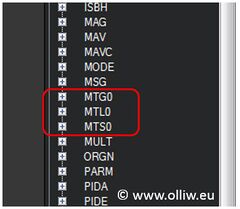
On the flight controller side, BetaPilot adds some dedicated data fields to ArduPilot's DataFlash logging (for DataFlash logs see Downloading and Analyzing Data Logs in Mission Planner).
Testing the Connection
The serial MAVLink connection can be tested in several ways. The following tests do not require that the vehicle is completely built and/or set up, and do not require that the vehicle is armed. For many of the tests it is also not even required that the gimbal is completely build or functioning.
MAVLINK field in STorM32 GUI
The [GUI:Dashboard] has a field named MAVLINK. It should display PRESENT.
Comment: MAVLINK is PRESENT means (only) that the STorM32 controller has a system ID and is receiving some MAVLink messages. It does not mean that the STorM32 controller makes any use of the received messages. The gimbal or camera component must be enabled for that.
STorM32-LINK field in STorM32 GUI
Both the [GUI:Dashboard] and the [GUI:Data Display] have a field which is related to the STorM32-Link. They should display PRESENT, AVAILABLE or OK.
Comment: STorM32-Link is PRESENT, AVAILABLE, OK means (only) that the STorM32 controller is receiving the STorM32-Link data and what their quality is. It does not mean that the STorM32-Link data are used. If it is used or not is determined by the setting in STorM32Link Configuration.
Mavlink Inspector in STorM32 GUI
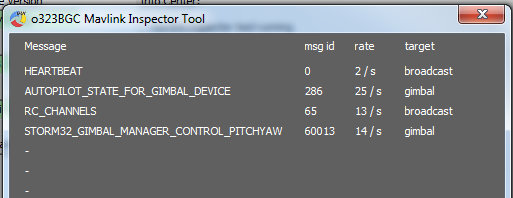
The [GUI:Mavlink Inspector Tool] displays the MAVLink messages which the STorM32 controller receives and can handle.
Comment: Only MAVLink messages are displayed which the STorM32 controller can handle. The fact that messages are displayed does not mean that the STorM32 controller does indeed handle these messages; this depends on the settings. All it means is that the STorM32 controller is receiving these messages. Also, not all messages which are send to the STorM32 gimbal are shown.
Comment: This screen shot shows the messages when the gimbal operates as gimbal manager, it will look differently in other cases.
MissonPlanner or QGroundControl
With the Gimbal component enabled, a MAVLink component named GIMBAL or GIMBALx (x = 2...6) should be present. If the Camera component is enabled, a component named CAMERAx (x = 1...6) should be present.
In MissionPlanner for instance:
MissonPlanner Messages Box
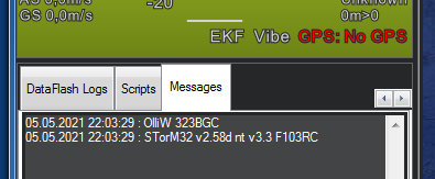
MissionPlanner's Messages box should show several text messages related to the STorM32 gimbal. In particular, a message like "STorM32 v2.40 nt v1.30 F103RC" informing about the STorM32 firmware version should be visible.
Comment: The messages shown depend on which component (autopilot, gimbal or camera) is selected in MissionPlanner. This can be a bit confusing. The STorM32 specific messages are seen only when the gimbal or camera component is selected. When the autopilot component is selected, the messages from BetaPilot are seen.
Campoint in MissonPlanner Status Box
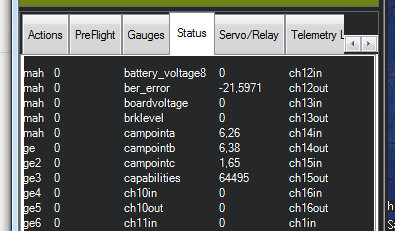
With the autopilot component selected in MissionPlanner, the campointa/b/c values in the Status box should show non-zero values and should move according to the movement of the gimbal.
Comment: If you select the gimbal component instead of the autopilot in MissionPlanner, then it will depend on your configuaration what you will see in MissionPlanner when the gimbal moves.
Mission Planner Payload Control Box
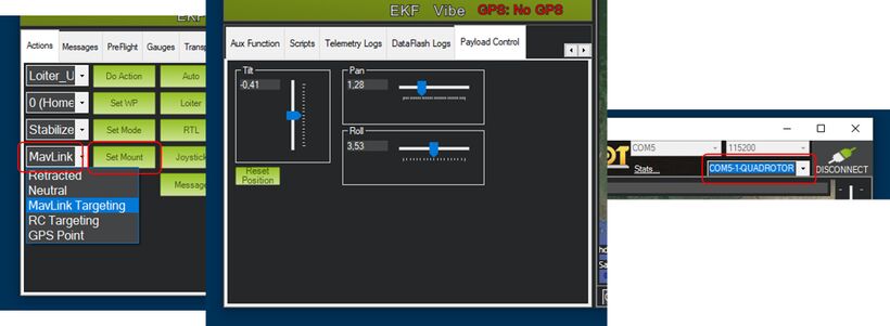
When the autopilot component is selected in MissionPlanner, the Payload Control box is available to control the pitch and yaw of the gimbal.
For this to work, the autopilot/mount needs to have been set into MAVLink targeting mode (MAV_MOUNT_MODE_MAVLINK_TARGETING). This can conveniently be achieved in MisssionPlanner through the Action box.
Comment: Be carefull with moving the sliders in the Payload Control box; small changes can lead to large gimbal movements.
Gimbal RC Targeting
When the autopilot/mount is in RC Targeting mode (which should be the default mode), the gimbal can be moved with the transmitter sticks.
Gimbal Point
MissionPlanner supports what it calls a 'gimbal point'. It is a blue point icon on the map, which indicates the estimated position at which the gimbal is looking at (see also e.g. https://github.com/ArduPilot/MissionPlanner/issues/1323). In order to activate it, the following ArduPilot parameters must be set:
Settings in ArduPilot:
- MNTx_STAB_ROLL = 0
- MNTx_STAB_TILT = 1
Using Gimbal Protocol V2
With BetaPilot installed, STorM32 MAVLink2 mount (MNTx_TYPE = 83) enabled, and Mavlink Gimbal Stream = “device status” selected, the flight controller works as a gimbal manager and the STorM32 gimbal as a gimbal device, according to the Gimbal Protocol v2 specification.
Since this protocol is not yet widely adopted, the communication is briefly described.
It is important to understand that all communication which is concerned with the control of the gimbal is with the gimbal manager, and not with the gimbal device directly. Since in our scenario the gimbal manager is implemented in BetaPilot, which runs on the flight controller, this essentially means that all communication is with the flight controller.
For the following let's assume the following system and component ids:
- flight controller: system id = 42, component id = 1 (MAV_COMP_ID_AUTOPILOT1)
- STorM32 gimbal: system id = 42, component id = 154 (MAV_COMP_ID_GIMBAL)
- GCS: system id = 255, component id = 190 (MAV_COMP_ID_MISSIONPLANNER)
Messages
The following messages are (minimally) of relevance.
Messages from the flight controller:
- HEARTBEAT of flight controller: This message should be waited for in order to discover the presence of the flight controller. No communication should be attempted before this heartbeat wasn't observed. This is not strictly required, but is good practice.
Messages from the gimbal manager and gimbal device:
- GIMBAL_MANAGER_STATUS: This is a key message. It reports the status of the gimbal manager and provides especially gimbal_id. This number is the MAVLink component id of the associated gimbal device, in our case gimbal_id = 154. This value is needed for all communication with the gimbal manager, and one thus needs to first observe this message (aka discover the gimbal manager). One should also memorize the source system and component ids (= sys_id, comp_id) of the message, as these are the target ids one should use when sending messages to the gimbal manager. In our case sys_id = 42, comp_id = 1.
- GIMBAL_MANAGER_INFORMATION: This message is also important. It reports the cap_flags flags, which describes the capabilities of the gimbal. Therefore, it also should be obtained before communicating with the gimbal manager. For that, a MAV_CMD_REQUEST_MESSAGE command should be send out as broadcast, which will make all gimbal managers in the system to respond. The GIMBAL_MANAGER_INFORMATION message belonging to our gimbal can be identified by the gimbal_id.
- GIMBAL_DEVICE_ATTITUDE_STATUS: This message is emitted by the gimbal device (= STorM32 controller) and reports especially the orientation of the camera. The messages belonging to our gimbal can be identified by the gimbal_id.
Messages to the gimbal manager:
- MAV_CMD_DO_GIMBAL_MANAGER_CONFIGURE: Before one can control the gimbal, one needs to ask for the rights to control the gimbal. This is accomplished by sending this command to the gimbal manager, with the primary and secondary control fields set appropriately. Note that the gimbal manager will reject any gimbal control messages which are not coming from a source which has the rights to control the gimbal. In our case we can send this command with sysid primary control = 255, compid primary control = 190, and the secondary control values set to 0. This gives the GCS the control rights. Note: we also can send the command with sysid primary control = -2, compid primary control = -2, which can be more convennient. You can confirm that the GCS got the control rights by inspecting the respective fields in the GIMBAL_MANAGER_STATUS message.
- GIMBAL_MANAGER_SET_PITCHYAW: This is the main message for controlling the gimbal. The STorM32 controller only supports setting the angles, not rates. Also, the GIMBAL_MANAGER_FLAGS_YAW_IN_VEHICLE_FRAME flag must be set.
Communication Protocol
The canonical procedure for starting the communication with the gimbal is thus as follows:
- Wait for HEARTBEAT from flight controller.
- Wait for GIMBAL_MANAGER_STATUS from gimbal manager. Memorize gimbal_id, sys_id, and comp_id.
- Request and wait for GIMBAL_MANAGER_INFORMATION. Memorize cap_flags.
- Send MAV_CMD_DO_GIMBAL_MANAGER_CONFIGURE to the gimbal manager, with sysid primary control = -2, compid primary control = -2.
- Now you can control the gimbal by sending GIMBAL_MANAGER_SET_PITCHYAW messages as desired.
The gimbal id in the messages/commands should be set to gimbal_id, and the target ids to sys_id and comp_id.
Notes:
- In principle, steps 2. and 3. should be swapped, i.e., one should first request and wait for GIMBAL_MANAGER_INFORMATION. The specification does not require gimbal managers to send out GIMBAL_MANAGER_STATUS voluntarily, in which case one needs to first request and wait for GIMBAL_MANAGER_INFORMATION in order to get gimbal_id, and then in the 3. step request a GIMBAL_MANAGER_STATUS stream. BetaPilot's gimbal manager however sends GIMBAL_MANAGER_STATUS voluntarily (as soon as it has discovered the STorM32 gimbal). This not only makes the protocol simpler but also provides significant benefits like adaptive emission rate.
- Step 3. might be skipped if the content of GIMBAL_MANAGER_INFORMATION is known a priory and for sure, or is not relevant.
- In the simple scenario of above, step 4. is also not mandatory. When BetaPilot's gimbal manager receives e.g. a GIMBAL_MANAGER_SET_PITCHYAW message and nobody else is currently in possession of the control rights (sysid primary control = 0, compid primary control = 0), then it grants the control rights to the source of the message, in our case the GCS. This too is not according to specification, but very handy.
With these notes in mind, with BetaPilot and only one gimbal in the system, the simplest startup procedure is thus:
- Wait for GIMBAL_MANAGER_STATUS. Memorize gimbal_id, sys_id, and comp_id.
- Now you can control the gimbal by sending GIMBAL_MANAGER_SET_PITCHYAW messages as desired.
Mount Mode
In addition to the settings whithin the gimbal protocol (and camera protocol), the behavior of the complete system, vehicle, gimbal and camera, depends also on the setting of the mount mode.
The mount mode is set by the command MAV_CMD_DO_MOUNT_CONFIGURE. The default mount mode should be set to MAV_MOUNT_MODE_MAVLINK_TARGETING. In other modes the control of the gimbal by the above gimbal messages might be restricted or modified.
Comment: Logically/conceptually, this mode is not part of any gimbal or camera protocol, as it can affect the behavior of all parts on the symbol, but such a mode is needed to determine the coordinated action of all components of the system. Currently there is no replacement available to the legacy mount mode, hence the older MOUNT messages are used.
