|
|
| Line 1: |
Line 1: |
| One of the most important steps is of course the proper tuning of the gimbal. However, it is also - unfortunately - the least straight-forward and most debatable step. No unique or universal tuning recipe seems to have emerged yet, and tuning remains an experimental process of trial-and-error. The following can hence only attempt to give some ideas. It is also necessarily very subjective, i.e. based on individual experiences on specific gimbals. Furthermore, a basic understanding by the operator is unavoidable, and the following is accordingly explanatory in parts.
| | The biggest problem for people new to brushless gimbal is finding the correct values of the PID parameters. A PID controller is a well known and frequently used method for calculating a new input value by measuring the difference between the current state compared with the target state, applying a formula to the difference and its result is the new input value. In theory after one such calculation the target state would be reached, but in reality the motor is not indefinitely fast. So in the next iteration there is a smaller error and a better input value will be calculated based on the current difference between actual and target. |
|
| |
|
| If your experience has led you to different tuning rules please feel free to share them (the [http://www.olliw.eu/storm32bgc-wiki/index.php5/Talk:Tunning_Guide Discussion] page could be a good place for that).
| | Due to this iterative approach all kind of bad things might happen. For example the gimbal might look down by 15°, our formula is: motorpower = 15° * 2W/°. Due to this amount of power the motor turns 30° instead of the expected 15°. So in the next iteration the direction is inversed to -15° * 2W/° = -30W (30W in the reverse direction). The effect would be a shaking of the motor around the 0° position. The formula used by a PID control algorithm is more advanced that above example and is optimized for quick reaction without overshooting the the target position (much). But even here, if the parameters are wrong, you get all kinds of weird movement patterns. |
|
| |
|
| == Tuning the PID Controller of one Axis ==
| | see [http://en.wikipedia.org/wiki/PID_controller|Wikipedia] for the details |
|
| |
|
| === Preliminaries === | | == Balancing the Gimbal == |
| The PID controller is the part of the firmware which controls the orientation (attitude) of the camera by using the measured attitude for driving the motors such that the camera stays put. It is assumed that the reader understands the basics of PID controllers; many introductions are available on the web. At this point the first, and maybe most important comment is at place:
| |
|
| |
|
| '''The PID tuning rules given in (essentially) all texts on PID controllers do NOT apply to brushless direct-drive gimbals!'''
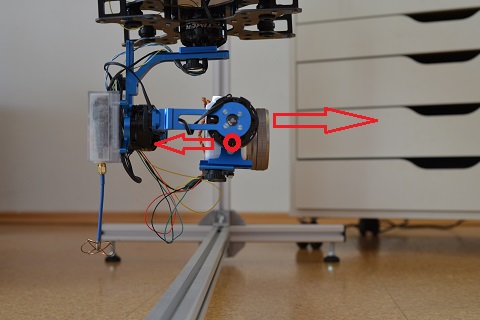
| | Before you do any tuning, the gimbal has to be balanced. Balancing means the center of gravity of the mounted camera is in the center of all three gimbal axis. This can be tested quite easily as it would mean that no matter how you move the camera, while the gimbal motors are turned off, the camera remains in that position. |
| | A perfectly balanced gimbal has multiple advantages |
|
| |
|
| So, the situation for brushless gimbals is somewhat different to that for the "usual" systems, and this obviously affects the tuning practice. Furthermore, although maybe termed PID in all cases it seems that the implemented PID controllers differ somewhat in their working; one probably should distinguish as follows:
| | * We want to move the camera with the RC stick. When the center of gravity would be below the pitch axis, the camera would try to get into the vertical position by itself, which sounds like a good idea at first sight, but as soon as we want to look downwards the motor needs to apply constant force to compensate this momentum. |
| | * If the gimbal as a whole is accelerated, the camera would move as well and again we would need to apply power against that movement. |
|
| |
|
| * AlexMos 2.3 and below, [http://www.rcgroups.com/forums/showthread.php?t=1978860 EvvGC]: These firmwares implement basically PD controllers, with a "weak" I term.
| |
| * [http://sourceforge.net/projects/brushless-gimbal-brugi/ BruGi], [http://www.rcgroups.com/forums/showthread.php?t=2059364 BGC32], AlexMos 2.4, o323bgc/STorM32bgc: These firmwares implement "full" PID controllers.
| |
|
| |
|
| '''''Comment:''' The AlexMos codes are of course not available, one can hence only speculate, however the various available descriptions/tutorials are telling.''
| | [[File:DSC_7111.jpg]] |
|
| |
|
| The good message is that the PID controllers in the second category of firmwares work by the very same basic principles, which means that the tuning recipes given for any of them may be used to tune STorM32-BGC gimbals (be aware however that this doesn't mean that PID values can be carried over; the units generally are different!). The less good message is that there seem to be two different tuning strategies, which may be called "low-PWM" and "high-PWM" tuning, and neither of them avoids experimenting. The "low-PWM" tuning resulted from experience for Gopro and larger gimbals; the "high-PWM" tuning has been described for micro gimbals. At this point it's not clear which one is generally better, or if any is the best at all.
| |
|
| |
| As a general tuning rule, consider:
| |
|
| |
| Don't overdo it. Better be a bit conservative.
| |
|
| |
| The first sentence is supposed to mean that while it's true that a proper tuning can lead to enormous performance gains and is mandatory for optimal operation it's also true that it is meaningless to adjust the parameters to their last digit. The second sentence reflects the fact that a PID controller which is aggressively tuned for a certain condition (e.g. battery voltage) is also very sensitive to changes in these conditions, i.e., is less robust.
| |
|
| |
| Finally, although it may be obvious and may appear a bit smart ass, it cannot be over emphasized that:
| |
|
| |
| The key to a good performance of the gimbal is a perfect mechanics and balance.
| |
|
| |
| Inspection of the various threads immediately confirms this point.
| |
|
| |
| === Basic PID Parameters ===
| |
| The basic PID controller parameters are {{GUI|P}}, {{GUI|I}}, {{GUI|D}}, and {{GUI|Vmax}}.
| |
| The parameter {{GUI|Vmax}} is known in other firmwares as the motor PWM or motor power.
| |
|
| |
| The o323bgc firmware provides also the parameters {{GUI|Pan}}, {{GUI|Voltage Correction}}, and {{GUI|Hold To Pan Transition Time}}. These are however not relevant for the basic tuning, and {{GUI|Pan}} should in fact be deactivated for tuning.
| |
|
| |
| [[File:1main.png|480px]]
| |
|
| |
| === Coarse Tuning Settings ===
| |
| For the basic tuning, the advanced tuning parameters should be deactivated.
| |
|
| |
| * {{GUI|Pan}} MUST be set to zero (or the hold mode ensured by other means, such as via the {{GUI|Pan Mode Control}} settings)
| |
| * {{GUI|Voltage Correction}} should be set to 0%
| |
| * the battery should neither be fully charged nor nearly discharged (i.e. have a voltage of around 3.7 V per cell)
| |
|
| |
| The first step is to obtain a basic, working tuning of all axes (coarse tuning). One should tune first the pitch axis, then roll, and then yaw. Ideally one would block the roll and yaw axes while tuning the pitch axis, and the yaw axis while tuning the roll axis. In any case make use of the {{GUI|Roll Usage}} and {{GUI|Yaw Usage}} parameters to avoid uncontrolled motion or even damage to the gimbal.
| |
|
| |
| Once the gimbal is coarsely tuned, one may proceed with fine tuning, which is entirely trial-and-error and no tuning recipe exists at all. Here the Data Display is most useful.
| |
|
| |
| === "Low-PWM" Tuning ===
| |
| The "low-PWM" tuning strategy starts from the recommendation to set {{GUI|Vmax}}, or motor power or PWM, as small as possible.
| |
|
| |
| The motor power should of course also be as large as needed to overcome the motor's cogging torque, friction or imperfections in the balance. This sets a lower limit to {{GUI|Vmax}}. Typical tuning guides are
| |
|
| |
| * [http://sourceforge.net/p/brushless-gimbal-brugi/wiki/PIDtuningguide/ http://sourceforge.net/p/brushless-gimbal-brugi/wiki/PIDtuningguide/]
| |
| * [https://bradatech.com/xPedRobo/shop/download/uploading_software_martinez_board.pdf https://bradatech.com/xPedRobo/shop/download/uploading_software_martinez_board.pdf], page 10
| |
| * [http://www.multi-rotor.co.uk/index.php?topic=2945.0 Quick how to tune guide for BRUGI/martinez brushless gimbals]
| |
| * [http://blgwiki.com/index.php?title=A_Tuning_Guide A Tuning Guide - Brushless Gimbal Wiki]
| |
| * PLEASE ADD HERE
| |
|
| |
| As said before, this recipe has emerged from the experience by several authors on Gopro and larger gimbals, and in this sense may be considered as "proven". Generally, the motor power must not be too small:
| |
|
| |
| The value of {{GUI|Vmax}}, or motor power or PWM, should not be below 65 or 25%.
| |
|
| |
| Lowering the {{GUI|Vmax}} value also diminishes the available angle resolution, and if it's too small the gimbal can't correct smoothly anymore.
| |
|
| |
| === "High-PWM" Tuning ===
| |
| The "high-PWM" tuning strategy starts from the recommendation to set {{GUI|Vmax}}, or motor power or PWM, as large as possible.
| |
|
| |
| The rational in this tuning is that a larger motor power makes the system react faster (allowing in principle a faster correction and hence smaller error angles) and be more robust against disturbances such as cogging torque, frictions, wind gusts and so on.
| |
|
| |
| The upper limit for {{GUI|Vmax}} is mainly determined by the heat produced in the motors. Obviously, the motors should not get too hot. In practical terms, one should be able to touch the motors for several seconds (10 sec or more). The motor heat is however not the only factor which determines the proper {{GUI|Vmax}} value. As with the other parameters, one needs to experiment. It may e.g. happen that with a too large {{GUI|Vmax}} one can't achieve a vibration free, good tuning, and a somewhat lower {{GUI|Vmax}} is much better.
| |
|
| |
| As regards {{GUI|P}}, {{GUI|I}}, {{GUI|D}}, these two procedures seem to work:
| |
| *'''Procedure A:''' Set {{GUI|I}} to a small value. Increase {{GUI|D}} and {{GUI|P}} alternately, step by step. The gimbal should not start to oscillate. Since it are only two parameters one will quickly find the best balance of large {{GUI|D}} and large {{GUI|P}}. Now turn up the {{GUI|I}} value until the gimbal starts to oscillate, and back off by some 10 %. Finally, experiment with all three values. The general goal should be to get a large {{GUI|I}} value.
| |
|
| |
| *'''Procedure B:''' Set {{GUI|P}} to zero or avery small value, and first adjust {{GUI|I}} and {{GUI|D}}. That is, increase {{GUI|I}} until the gimbal oscillates, then increase {{GUI|D}} to damp the oscillation. Repeat until neither increasing {{GUI|I}} nor {{GUI|D}} stops gimbal oscillations. Now also use {{GUI|P}}, and experiment with all three values until the result is satisfying. The general goal should be to get a large {{GUI|I}} value.
| |
|
| |
| '''''Tip:''' Vibrations or oscillations of the gimbal can be nicely seen in the DataDisplay's accelerometer panel.''
| |
|
| |
| == Voltage Correction ==
| |
| The voltage correction mechanism in o323bgc attempts to compensate the effects by a varying battery voltage on the PID controller tuning. It does it by modifying the actual motor power. i.e. {{GUI|Vmax}} values proportionally to the voltage change. The proportionality factor is given by the parameter {{GUI|Voltage Correction}}.
| |
|
| |
| For instance, with a {{GUI|Voltage Correction}} of 100%, a drop in the battery voltage by 25% leads to an increase of the actually used Vmax value by 25%. With a {{GUI|Voltage Correction}} of 50%, a voltage drop by 25% leads to a 12.5% increase in Vmax, and so on.
| |
|
| |
| The mechanism can significantly reduce the dependence of the gimbal performance on the battery voltage. It can however not accomplish what could be achieved with a truly constant (regulated) voltage.
| |
|
| |
| == Tuning the Pan Speed ==
| |
|
| |
| For the STorM32-BGC the pan (follow) mode is in some ways independent on the PID controller. The PID tuning must thus be done with the pan mode deactivated. However, on the other hand, once the PID controller is tuned, the pan speed can be easily adjusted without having to touch the PID controller any further. This is probably one of the appealing features of the STorM32-BGC. Accordingly, the discussion of the hold and pan modes is deferred to a later chapter.
| |
|
| |
| == Understanding the Parameters ==
| |
|
| |
| Maybe useful references (from the German FPVC forum):
| |
| * http://fpv-community.de/showthread.php?20795-Brushless-Gimbal-Controller-SOFTWARE&p=382163&viewfull=1#post382163
| |
| * http://fpv-community.de/showthread.php?20795-Brushless-Gimbal-Controller-SOFTWARE&p=381584&viewfull=1#post381584
| |
| * http://fpv-community.de/showthread.php?20795-Brushless-Gimbal-Controller-SOFTWARE&p=381513&viewfull=1#post381513
| |
|
| |
|
| == Next step - RC Inputs == | | == Next step - RC Inputs == |
The biggest problem for people new to brushless gimbal is finding the correct values of the PID parameters. A PID controller is a well known and frequently used method for calculating a new input value by measuring the difference between the current state compared with the target state, applying a formula to the difference and its result is the new input value. In theory after one such calculation the target state would be reached, but in reality the motor is not indefinitely fast. So in the next iteration there is a smaller error and a better input value will be calculated based on the current difference between actual and target.
Due to this iterative approach all kind of bad things might happen. For example the gimbal might look down by 15°, our formula is: motorpower = 15° * 2W/°. Due to this amount of power the motor turns 30° instead of the expected 15°. So in the next iteration the direction is inversed to -15° * 2W/° = -30W (30W in the reverse direction). The effect would be a shaking of the motor around the 0° position. The formula used by a PID control algorithm is more advanced that above example and is optimized for quick reaction without overshooting the the target position (much). But even here, if the parameters are wrong, you get all kinds of weird movement patterns.
see [1] for the details
Balancing the Gimbal
Before you do any tuning, the gimbal has to be balanced. Balancing means the center of gravity of the mounted camera is in the center of all three gimbal axis. This can be tested quite easily as it would mean that no matter how you move the camera, while the gimbal motors are turned off, the camera remains in that position.
A perfectly balanced gimbal has multiple advantages
- We want to move the camera with the RC stick. When the center of gravity would be below the pitch axis, the camera would try to get into the vertical position by itself, which sounds like a good idea at first sight, but as soon as we want to look downwards the motor needs to apply constant force to compensate this momentum.
- If the gimbal as a whole is accelerated, the camera would move as well and again we would need to apply power against that movement.
Next step - RC Inputs
With these settings we have a self leveling gimbal. No matter what movements the gimbal support is undergoing, the camera remains stable. While this might be perfectly sufficient for basic operation, normally the gimbal shall also be moved via a RC stick or, on a hand-held gimbal, via a joystick, or functions such as switching between hold and pan modes or releasing the shutter of the camera remotely are desired.
You can learn about these possibilities in the next chapters; continue with Configure the RC Input.
