NT Camera: Difference between revisions
| Line 52: | Line 52: | ||
Once you have your cable and transmitter configured as above connect your receiver, or flight controller, and test it out. It should work before moving onto the next section. | Once you have your cable and transmitter configured as above connect your receiver, or flight controller, and test it out. It should work before moving onto the next section. | ||
{{COMMENT|Leave your transmitter as configured for the duration of this instruction. If it passes function test of the above it will work as below.}} | {{COMMENT|Leave your transmitter as configured for the duration of this instruction. If it passes function test of the above it will work as described below.}} | ||
=== CC3D NT IMU, STorM32 and Git2 Camera Integration === | === CC3D NT IMU, STorM32 and Git2 Camera Integration === | ||
Revision as of 21:29, 20 July 2016
Since firmware version v2.04e, NT camera modules are supported.
The NT camera module allows to remote control a camera. It thus serves a similar purpose as the various RC camera remote control modules, such as CAMremote, CamCntrl, IR Remote Shutter Controller, and all the others. Instead of listening to a servo PWM signal however, it listens to the data on the NT bus. It is thus usually connected to the NT bus near the camera NT IMU module, which yields extremely slim wiring schemes (see here). The camera remote control is associated with the IR Camera Control function in the [Functions] tab.
In addition, the NT camera module also acts as a "PWM out" module. That is, it outputs an additional servo PWM signal, which is an exact mirror of the PWM output signal available on the STorM32 board (when set up accordingly). This PWM signal is associated with the Pwm Out Control function in the [Functions] tab.
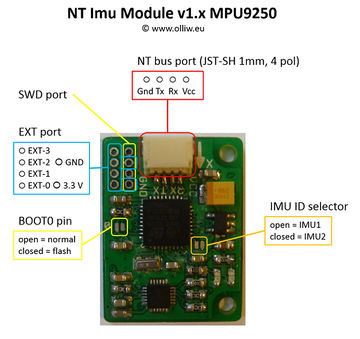
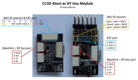
Dedicated NT camera hardware has not yet emerged, but the NT camera function is integrated into the NT IMU firmware. This means that those NT IMU modules which expose extra pins can simultaneously be used also as NT camera modules. Specifically this are the "big" v1.x NT IMU module and the CC3D Atom based modules.
NT Camera Support by NT IMU Modules
In v2.05e, three NT camera related signals are available at the EXT port pins of NT IMU modules, namely:
- pin EXT-3: IR Camera standard servo PWM signal (with ca. 60 Hz frequency)
- pin EXT-2: IR Camera pulse, 50 ms off/on/off
- pin EXT-1: Pwm Out standard servo PWM signal (with ca. 60 Hz frequency)
The two "IR Camera" signals are determined by the settings related to the IR Camera Control function; see also Advanced Functions: IR Camera Remote Control. The "Pwm Out" signal is affected by the settings for the Pwm Out Control function, see Advanced Functions: Pwm Out. For hardware reasons the NT IMU modules cannot drive IR LEDs, and this remote control option is thus not available with them.
The IR Camera PWM signal could directly feed cameras, which can be triggered by such signals, such as the Gitup Git2 or Foxeer Legend 1, or could be connected to a standard RC camera remote control module, such as those mentioned in the introduction.
The IR Camera pulse signal can be used for all sorts of purposes. For instance, it could be connected to a semiconductor relais to drive an IR LED, or to shorten some pins on a USB remote.
The pin assignment on the v1.x NT IMU and the CC3D Atom modules is as follows:
Gitup Git2
General Camera Remote Operation
The Git2 has the ability to receive a PWM signal via its Micro HDMI port from your receiver to control video recording and photo triggering. As to the specifics they can be found on the Gitup Site but in general a 3 position switch will be used on your transmitter. The middle position will be setup up as 1500µs and will do nothing. Low position, < 1250µs, will start recording video when switched. High position, > 1800µs, will take one photo when switched. If your transmitter channel is setup as 0%, 50%, 100% (or -100,0,100) for Low, Mid, and High you should be fine.
Links:
- http://www.gitup.com/en/blog/22_Git2-Remote-Shutter-for-FPV.html
- http://www.rcgroups.com/forums/showpost.php?p=34538383&postcount=3443
Cable Information
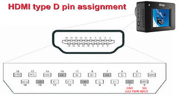
Gitup does have a Remote Shutter cable available. If you choose to make your own please follow the pinouts for the Micro HDMI (type D), not Mini or full size because they are different as shown [here][1].
- Signal In: Micro HDMI Pin 2 (Usually marked as Utility or Reserved on a pin out)
- Signal Gnd: Micro HDMI Pin 4 (Marked as TMDS Data2 Shield, or any other shield pin. Even the connector case works)
Just as a note, the Git2 uses its Mini USB port for both Video Out and Power In to charge or power the camera. While Gitup also provides this cable the FPV Cable made for the GoPro works as well. At the time of this writing Gitup is working on a combo board / cable, which will contain both the HDMI and USB connectors.
Cable and Camera Function Test
Once you have your cable and transmitter configured as above connect your receiver, or flight controller, and test it out. It should work before moving onto the next section.
Comment: Leave your transmitter as configured for the duration of this instruction. If it passes function test of the above it will work as described below.
CC3D NT IMU, STorM32 and Git2 Camera Integration
Notes:
- This section will be based on the use of the Mini CC3D Atom and has been tested. Other NT IMU modules with integrated NT Camera function should be similar.
- This is only one example of the many available options from the STorM32.
- Your STorM32 and NT IMU need to be correctly communicating. Gimbal not necessarily needs to be "tuned".
Control Overview
The Mini CC3D Atom has a port with pins labeled GND, 5V and PWM6 to PWM1, where PWM3 corresponds to EXT-3, and PWM2 to EXT-1. The STorM32 and CC3D firmware makes use of two functions found in the [GUI:Functions] tab of the o323BGCTool GUI:
- IR Camera Remote Control: We will use this.
- PWM Output: Future / other use.
Wiring
- Connect your receiver, or flight controller, to one of the seven STorM32 RC ports (RC-0 through RC2-3), or any other input channel (see Inputs and Functions).
- Connect the Git2 "Remote Shutter" cable to the PWM3 and Gnd pins on the Mini CC3D Atom.
o323BGCTool GUI Setup
Under the [GUI:Functions] Tab use the column for IR Camera Control and set as follows:
- IR Camera Control = “Rc-0” (Or whatever port you connect up to the STorM32 above)
- Camera Model = “Git2RC”
- IR Camera Setting #1 = “shutter”
- IR Camera Setting #2 = “video on/off”
- Time Interval: Setting this to 0 (off) will result in one photo taken when switched from Mid to High. If set to other than 0 continuous photos will be taken. The time period is from the start of the first photo to the start of the second photo, etc.
Foxeer Legend 1
To be filled.
RunCam 2
To be filled.
CAMremote
To be filled.


