Getting Started with T-STorM32: Difference between revisions
| Line 32: | Line 32: | ||
== NT Motor-Encoder Module Configuration == | == NT Motor-Encoder Module Configuration == | ||
As mentioned before the combination of a NT motor-encoder module with its motor is treated as one unit. This makes sense logically, and has its advantages, but also its disadvantage. | |||
The first step thus consists of configuring the NT motor-encoder modules, for each axis. Two parameters need to be set, namely the number of motor poles, and the offset between mechanical and electrical angle. These values are stored permanently in the NT motor-encoder module. For DIY builds one also needs to check beforehand that the magnet and encoder are located appropriately, i.e., that the distance between them results in appropriate signal strengths and that they are centered properly. In addition, the NT motor-encoder modules firmware includes options to run various test sequences, which provide detailed information on the motor properties and performance. | |||
Currently, these configuration steps are not possible via the GUI, but require the use of a standard terminal, such as [http://www.der-hammer.info/terminal/index.htm HTerm]. It can be done in two ways: | |||
* The NT motor-encoder module is connected to a STorM32 main board (via the NT bus), and the STorM32 main board is connected to a PC, either via the main board's USB port or the UART port. In that case the main board has first to be put into a pass-through mode by sending a special command to it. It then works as tunnel connecting the PC with the NT module. | |||
* The NT motor-encoder module is connected on its NT port directly to a PC via a USB-TTL adpater, pretty much as one would do for the [Live Recording] feature. | |||
== Basic Controller Configuration == | == Basic Controller Configuration == | ||
== First Startup == | == First Startup == | ||
Revision as of 13:31, 14 March 2017
This is a first attempt of a documentation for the T-STorM32. Will be relatively disorganized at first.
Concept
The encoder support builds on the NT concept, and especially on the possibility of connecting separate NT motor modules to the NT bus. T-STorM32 makes use of dedicated NT motor modules, which include encoders. They shall be called NT motor-encoder modules (or should we call them TNT motor modules ?).
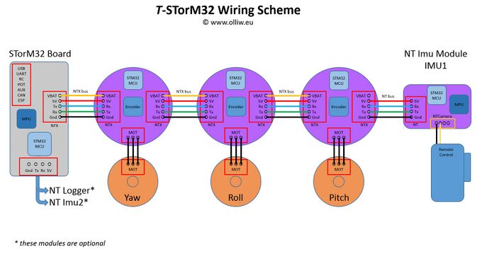
The T-STorM32's concept consists of a main controller board and three NT motor-encoder modules, one for each axis. The motor drivers on the main STorM32 board cannot be used, and unlike with Basecam/Alexmos, it is also not possible to connect encoders to the main STorM32 board. The NT motor-encoder modules are connected to the NT bus, and battery power. The NTX bus has thus been introduced, which carries both the NT bus signals and the battery power lines.
The concept, also sketching a typical wiring scheme, thus looks as this:
From the perspective of the main controller, the NT motor-encoder module and motor associated to one axis is regarded as one combined unit. This implies a two-step setup procedure: First the "NT motor-encoder module + motor" unit is configured, and then the firmware in the main controller board.
Ordering Information
Things to have at minimum:
- STorM32-BGC board
- NT IMU module and matching cable
- three NT Motor-Encoder modules and matching cables
- USB-to-serial adapter
The need for the STorM32 board, the NT IMU module, and the three NT motor-encoder modules should be obvious from the concept scheme. The USB-to-serial adapter is required for upgrading the STorM32 main board to the latest firmware. It is however also extremely useful for employing the Live Recording feature.
Supported Gimbals
T-STorM32 currently supports the following setups:
- 3-axis with camera IMU: One NT IMU, mounted to the camera, and three NT motor-encoder modules.
The T-STorM32 allows connecting a 2nd IMU (IMU2). However, its data are read but not used at all. It's there only to help e.g. with vibration analyses. Connecting a 3rd IMU (IMU3) doesn't harm, but it is ignored completely, i.e. not even its data are read.
NT Motor-Encoder Module Configuration
As mentioned before the combination of a NT motor-encoder module with its motor is treated as one unit. This makes sense logically, and has its advantages, but also its disadvantage.
The first step thus consists of configuring the NT motor-encoder modules, for each axis. Two parameters need to be set, namely the number of motor poles, and the offset between mechanical and electrical angle. These values are stored permanently in the NT motor-encoder module. For DIY builds one also needs to check beforehand that the magnet and encoder are located appropriately, i.e., that the distance between them results in appropriate signal strengths and that they are centered properly. In addition, the NT motor-encoder modules firmware includes options to run various test sequences, which provide detailed information on the motor properties and performance.
Currently, these configuration steps are not possible via the GUI, but require the use of a standard terminal, such as HTerm. It can be done in two ways:
- The NT motor-encoder module is connected to a STorM32 main board (via the NT bus), and the STorM32 main board is connected to a PC, either via the main board's USB port or the UART port. In that case the main board has first to be put into a pass-through mode by sending a special command to it. It then works as tunnel connecting the PC with the NT module.
- The NT motor-encoder module is connected on its NT port directly to a PC via a USB-TTL adpater, pretty much as one would do for the [Live Recording] feature.
