Flashing OlliW's NT Modules: Difference between revisions
| (25 intermediate revisions by the same user not shown) | |||
| Line 1: | Line 1: | ||
On all OlliW | On nearly all "OlliW" NT modules the BOOT0 pin is exposed as a solder jumper, and each module can thus be first-time flashed using the STorM32 main board. They of course also could be first-time flashed using a standard USB-TTL adapter. Most modules also have the SWD pins exposed, which allows a first-time flashing via a ST-Link adapter. All three flashing methods are fully supported by the GUI. Any subsequent flashing (updating) can be performed using the much simpler procedures described in [[Updating the Firmware of NT Modules]]. | ||
__TOC__ | __TOC__ | ||
== First-Time Flashing via STorM32 USB Port == | |||
'''1.''' Connect the STorM32 board via its USB port to the PC. | |||
'''2.''' '''''Important:''''' Find the BOOT0 solder jumper on the NT module and close it. Do '''''not''''' yet connect the NT module to the STorM32 board. | |||
'''3.''' In the STorM32 GUI go to the {{GUI|Flash Firmware}} tab and choose your settings: | |||
:* In the combo boxes {{GUIFIELD|Board}} and {{GUIFIELD|Firmware Version}} select the correct NT module and the desired firmware version. | |||
:* In the {{GUIFIELD|STM32 Programmer}} field select {{GUIPARAM|System Bootloader via STorM32 USB port}}. | |||
:* In the {{GUIFIELD|Port}} field select the COM port which the STorM32 board is connected to. | |||
:[[File:Storm32-wiki-nt-flash-firmware-storm32usb.jpg|640px]] | |||
'''4'''. Hit the {{GUIFIELD|Flash Firmware}} button. | |||
'''5'''. A message box will open and ask you to connect the NT module to the STorM32 board. Do so, and hit the {{GUIFIELD|OK}} button. Note: Only one NT module must be connected to the StorM32 board. Also, its BOOT0 solder jumper must be closed. | |||
'''6'''. Now a black window (DOS console) should open and run the flash loader program. Wait until it is finished (takes some seconds). | |||
'''7'''. '''''Important:''''' Do not forget to open the BOOT0 solder jumper on the NT module. The NT module is now ready for usage. | |||
== First-Time Flashing Using a USB-TTL Adapter == | == First-Time Flashing Using a USB-TTL Adapter == | ||
'''1.''' You will need a standard USB-TTL adapter. Ensure that it is working (drivers installed, etc.). | '''1.''' You will need a standard USB-TTL adapter (see [[STorM32_FAQ#Which USB-TTL adapter should I use.3F|FAQ: Which USB-TTL adapter should I use?]]). Ensure that it is working (drivers installed, etc.). | ||
'''2.''' Connect the | '''2.''' Connect the USB-TTL adapter to the NT bus pins on the NT bus connector. Do not yet power the NT module. | ||
'''3.''' Find the BOOT0 solder | '''3.''' '''''Important:''''' Find the BOOT0 solder jumper on the NT module and close it. | ||
:[[File:Storm32-nt-firmware-first-time-flashing-01.jpg|640px]] | :[[File:Storm32-nt-firmware-first-time-flashing-01.jpg|640px]] | ||
'''4.''' Now power up the NT module, e.g. by connecting the NT bus connector's VCC pin to the 3.3 V or 5 V pin (either is fine) on the USB-TTL adapter. | '''4.''' Now power up the NT module, e.g., by connecting the NT bus connector's VCC pin to the 3.3 V or 5 V pin (either is fine) on the USB-TTL adapter. | ||
'''5.''' | '''5.''' In the STorM32 GUI go to the {{GUI|Flash Firmware}} tab and choose your settings: | ||
:* In the combo boxes {{GUIFIELD|Board}} and {{GUIFIELD|Firmware Version}} select the correct NT module and the desired firmware version. | |||
:* In the {{GUIFIELD|STM32 Programmer}} field select {{GUIPARAM|System Bootloader @ UART1}}. | |||
:* In the {{GUIFIELD|Com Port}} field select the COM port which your USB-TTL adapter is connected to. | |||
'''7.''' | :[[File:Storm32-nt-firmware-first-time-flashing-gui-screen-02.jpg|640px]] | ||
'''6'''. Finally, hit the {{GUIFIELD|Flash Firmware}} button. | |||
'''7'''. Now a black window (DOS console) should open and run the flash loader program. Wait until it is finished (takes some seconds). | |||
'''8'''. '''''Important:''''' Do not forget to open the BOOT0 solder jumper on the NT module. The NT module is now ready for usage. | |||
== First-Time Flashing Using SWD == | == First-Time Flashing Using SWD == | ||
| Line 29: | Line 59: | ||
'''2.''' Connect the programmer to the SWD pins on the NT module. | '''2.''' Connect the programmer to the SWD pins on the NT module. | ||
'''3.''' | '''3.''' In the GUI go to the {{GUI|Flash Firmware}} tab and choose your settings. It should look something like this: | ||
:[[File:Storm32-nt-firmware-first-time-flashing-swd-gui-screen-02.jpg|640px]] | |||
'''4.''' Push the {{GUIFIELD|Flash Firmware}} button. | |||
''' | '''5.''' Now a black window (DOS console) should open and run the ST-Link loader program, as shown in the screenshot. Wait until it's finished (takes some seconds). The NT module will be reset and start running. | ||
:[[File:GUI_Flash_4.jpg|640px]] | :[[File:GUI_Flash_4.jpg|640px]] | ||
Latest revision as of 04:38, 3 June 2018
On nearly all "OlliW" NT modules the BOOT0 pin is exposed as a solder jumper, and each module can thus be first-time flashed using the STorM32 main board. They of course also could be first-time flashed using a standard USB-TTL adapter. Most modules also have the SWD pins exposed, which allows a first-time flashing via a ST-Link adapter. All three flashing methods are fully supported by the GUI. Any subsequent flashing (updating) can be performed using the much simpler procedures described in Updating the Firmware of NT Modules.
First-Time Flashing via STorM32 USB Port
1. Connect the STorM32 board via its USB port to the PC.
2. Important: Find the BOOT0 solder jumper on the NT module and close it. Do not yet connect the NT module to the STorM32 board.
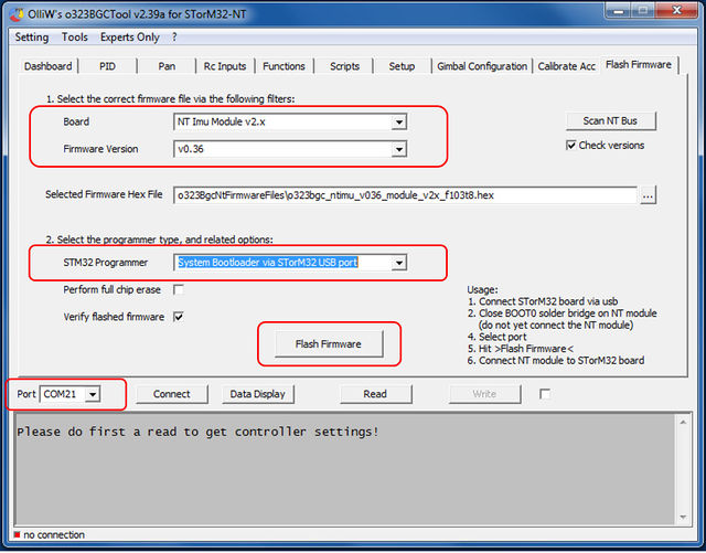
3. In the STorM32 GUI go to the [GUI:Flash Firmware] tab and choose your settings:
- In the combo boxes [Board] and [Firmware Version] select the correct NT module and the desired firmware version.
- In the [STM32 Programmer] field select "System Bootloader via STorM32 USB port".
- In the [Port] field select the COM port which the STorM32 board is connected to.
4. Hit the [Flash Firmware] button.
5. A message box will open and ask you to connect the NT module to the STorM32 board. Do so, and hit the [OK] button. Note: Only one NT module must be connected to the StorM32 board. Also, its BOOT0 solder jumper must be closed.
6. Now a black window (DOS console) should open and run the flash loader program. Wait until it is finished (takes some seconds).
7. Important: Do not forget to open the BOOT0 solder jumper on the NT module. The NT module is now ready for usage.
First-Time Flashing Using a USB-TTL Adapter
1. You will need a standard USB-TTL adapter (see FAQ: Which USB-TTL adapter should I use?). Ensure that it is working (drivers installed, etc.).
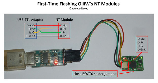
2. Connect the USB-TTL adapter to the NT bus pins on the NT bus connector. Do not yet power the NT module.
3. Important: Find the BOOT0 solder jumper on the NT module and close it.
4. Now power up the NT module, e.g., by connecting the NT bus connector's VCC pin to the 3.3 V or 5 V pin (either is fine) on the USB-TTL adapter.
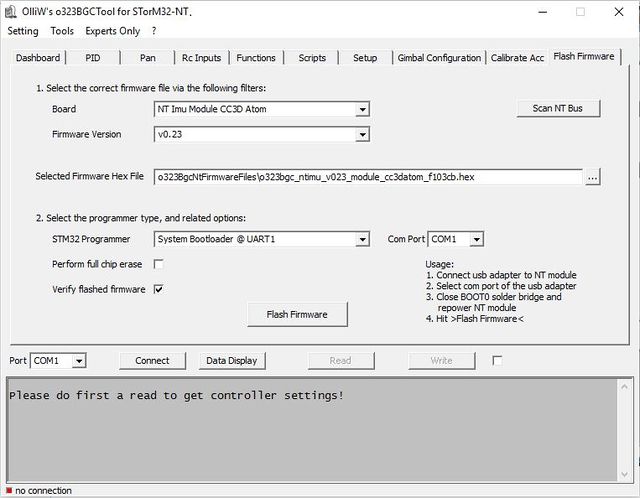
5. In the STorM32 GUI go to the [GUI:Flash Firmware] tab and choose your settings:
- In the combo boxes [Board] and [Firmware Version] select the correct NT module and the desired firmware version.
- In the [STM32 Programmer] field select "System Bootloader @ UART1".
- In the [Com Port] field select the COM port which your USB-TTL adapter is connected to.
6. Finally, hit the [Flash Firmware] button.
7. Now a black window (DOS console) should open and run the flash loader program. Wait until it is finished (takes some seconds).
8. Important: Do not forget to open the BOOT0 solder jumper on the NT module. The NT module is now ready for usage.
First-Time Flashing Using SWD
1. You will need a ST-Link V2 Programmer or similar. Ensure that it is working (drivers installed, etc.).
2. Connect the programmer to the SWD pins on the NT module.
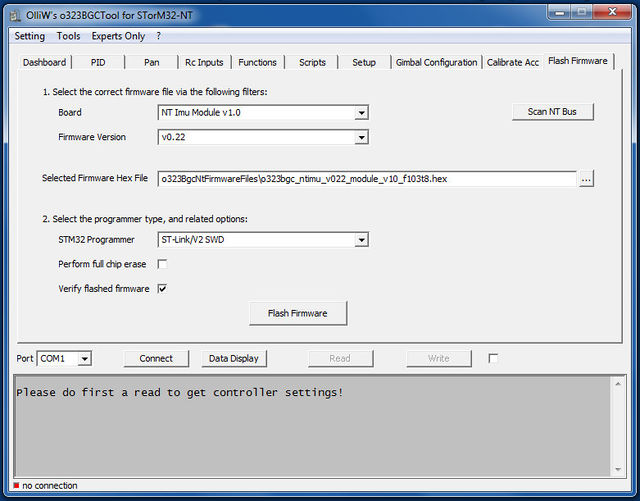
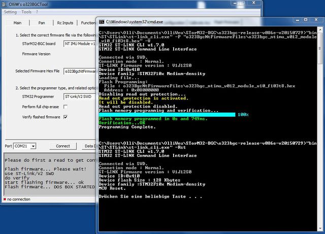
3. In the GUI go to the [GUI:Flash Firmware] tab and choose your settings. It should look something like this:
4. Push the [Flash Firmware] button.
5. Now a black window (DOS console) should open and run the ST-Link loader program, as shown in the screenshot. Wait until it's finished (takes some seconds). The NT module will be reset and start running.
Updating Firmware
For updating the NT firmware you may again use the methods described before, but preferably the "canonical" procedure described in Updating the Firmware of NT Modules.
