Evaluating Vibrations and Optimizing Damper Systems: Difference between revisions
No edit summary |
|||
| Line 1: | Line 1: | ||
For aerial video applications, one of the most difficult aspect of a DIY gimbal system is to achieve a low level of vibration and a well working damping system. The first reaction of most users to artefacts such as micro vibs or jello in the video seems to be "better PID tuning", while in fact the secret sauce of a well working system usually lies not in the PID tuning | For aerial video applications, one of the most difficult aspect of a DIY gimbal system is to achieve a low level of vibration and a well working damping system. The first reaction of most users to artefacts such as micro vibs or jello in the video seems to be "better PID tuning", while in fact the secret sauce of a well working system usually lies not in the PID tuning, but the copter's vibration level and construction of the gimbal damping system. | ||
Unfortunately, when it comes to the latter aspects the current approach available to us DIY guys is essentially trial-and-error, which at times can be frustrating. The STorM32 NT thus aims at providing tools to alleviate the situation. This is still an effort in progress, meaning that the best set of tools and/or best set of recipes to achieve the goals have not yet been established. However, some tools and procedures have emerged. | Unfortunately, when it comes to the latter aspects the current approach available to us DIY guys is essentially trial-and-error, which at times can be frustrating. The STorM32 NT thus aims at providing tools to alleviate the situation. This is still an effort in progress, meaning that the best set of tools and/or best set of recipes to achieve the goals have not yet been established. However, some tools and procedures have emerged. | ||
Revision as of 11:55, 22 September 2016
For aerial video applications, one of the most difficult aspect of a DIY gimbal system is to achieve a low level of vibration and a well working damping system. The first reaction of most users to artefacts such as micro vibs or jello in the video seems to be "better PID tuning", while in fact the secret sauce of a well working system usually lies not in the PID tuning, but the copter's vibration level and construction of the gimbal damping system.
Unfortunately, when it comes to the latter aspects the current approach available to us DIY guys is essentially trial-and-error, which at times can be frustrating. The STorM32 NT thus aims at providing tools to alleviate the situation. This is still an effort in progress, meaning that the best set of tools and/or best set of recipes to achieve the goals have not yet been established. However, some tools and procedures have emerged.
Conceptional
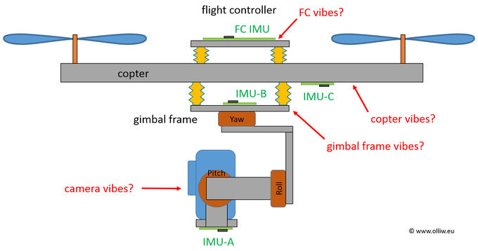
The basic idea of the STorM32's vibration and damping system analysis is sketched in the following picture.
Flight controller often provide options for analyzing the copter's vibrations. However, the disadvantage is obvious: In most cases it doesn't see the real copter vibrations, since it is mounted with some dampers. What matters are the vibrations at the camera, which is "far away" from the flight controller. That is, in a technical language, the transfer functions for the copter's vibrations to the flight controller or the camera are substantially different. For a complete vibration analysis one needs to know the vibrations on the copter, on the gimbal frame, and the camera. It is pointed out that only with knowing the vibrations on the copter and the gimbal frame, the performance of a gimbal damping system can actually be assessed.
That's the basic idea of the STorM32's three IMU setup, to provide us with a means to properly evaluate the vibrations and especially the gimbal damping system, which hopefully will allow us to get better gimbals.
The offered mechanisms however can also be used in other ways, e.g. for balancing motors and propellers. The possibilities are only limited by our creativity :).
Comment: In order to avoid confusion, this clarification: In the above sketch the IMU on the gimbal frame is named IMU-B and that on the copter IMU-C. Depending on the user's setup either could be the 2nd IMU (in the terminology of the STorM32 gimbal controller).
The following video explains that too, and also shows possible uses of the NTLoggerTool and Blackbox Explorer.
Basic Physics
The physics of vibrations and damper systems is elementary, and quite many aspects can be properly inferred by applying basic laws of physics. Surprisingly, it seems very rarely been done. In this chapter only one simple, but crucial point shall be pointed out:
The vibration dampers, as we like to call them, do not actually damp vibrations.
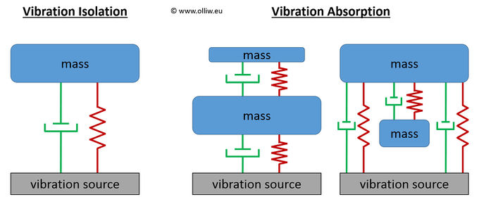
Before explaining that, it may be useful to first introduce the two general approaches of vibration isolation and vibration absorption (this classification seems to be widely, but not generally, accepted):
Vibration Isolation: The system is separated from a vibrating source by some flexible pieces of something (which we call dampers). Physically it is described as to consist of a damping element, spring element, and a mass of payload.
Vibration Absorption: The system is separated from a vibrating source by some dampers, with in addition a second mass of payload attached to the primary mass via some further dampers.
The gimbal damper system by itself constitutes a vibration isolation system. However, if the stiffness of the gimbal is taken into account, the copter + gimbal frame + camera system is rather reminiscent of a vibration absorption system (but with swapped roles of the masses). Anyway, let's assume a perfectly stiff gimbal, and let's talk about the gimbal dampers as a vibration isolation system.
Physically, the item which we commonly call a damper is a combination of a damping element and a spring element. The most crucial points to realize are these. First:
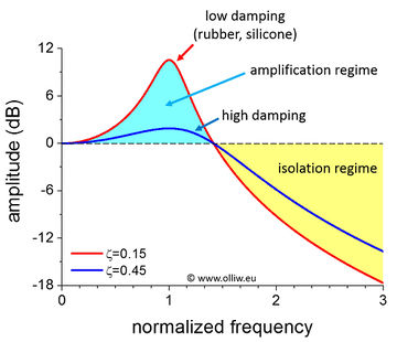
The damping coefficient of (most) vibration dampers is relatively low.
You may confirm that easily yourself by using google. The damping coefficient of e.g. rubber is somewhere in the range of few 0.1 or less. You may also easily confirm that by a simple test: Tip your gimbal, and you will see it swinging back and forth a couple of times. The necessary consequence of that is, second:
The vibration damper does not always reduce the vibrations.
In some frequency range the vibrations are actually substantially amplified.
This latter point makes the gimbal damping issue so complicated, because a good vibration reduction in some frequency range is payed for by some substantial amplification in vibrations in a lower frequency range. The situation is shown in this picture:
3rd IMU
As discussed in the chapter Conceptional, the evaluation of all vibrations relevant to the gimbal performance asks for 3 IMUs. The STorM32 NT thus supports this, in the following way:
The labeling of the three IMUs is as in the above figure. The three-IMU support is then constrained by these rules:
- Two of the IMUs must be NT IMU modules, and one IMU must be a traditional I2C-based IMU.
- The I2C-based IMU can be either the on-board IMU or an external IMU module connected to the I2C#2 port.
- As usual for NT, IMU-A must be the 1st NT IMU module, or IMU1, respectively.
Thus, these four configurations are possible:
- IMU-B = 2nd NT IMU module, IMU-C = on-board IMU
- IMU-B = 2nd NT IMU module, IMU-C = external I2C-based IMU at I2C#2
- IMU-B = on-board IMU, IMU-C = 2nd NT IMU module
- IMU-B = external I2C-based IMU at I2C#2, IMU-C = 2nd NT IMU module
Which configuration is in use, is determined by the setting of the parameter Imu3 Configuration in the [GUI:Expert Tool], as well as by whether an external IMU is connected to the I2C#2 port or not.
Comment: Currently only the last two configurations, where IMU-C is a NT IMU module, are supported.
Analysis Tools
The STorM32 NT project includes a range of hardware and software tools, which help tremendously in analyzing all sort of things, vibration issues would be one of them.
NT Logger
This piece of hardware can be connected to the NT bus and records all data on its Tx line on a micro SD card. For further info see the article NT Data Logging.
NTLoggerTool
This piece of software, written with PyQT and pyqtgraph, is the STorM32 developer's main tool to inspect recorded data. The data can come from various sources:
- Data recorded with the NT logger on a SD card
- Data recorded with the DataDisplay of the o323BGCTool GUI
- Live-recording
For further info see the article NT Data Logging.
Blackbox Explorer for STorM32
The NTLoggerTool allows us to convert the data into Blackbox Explorer compatible .cfl files. The Blackbox Explorer allows us then to overlay the recorded video with the logged data, and thus to directly correlate any video artifacts with features in the logged data.


