Getting Started: Difference between revisions
No edit summary |
mNo edit summary |
||
| Line 107: | Line 107: | ||
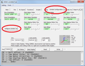
# Change to the {{GUI|Gimbal Configuration tab}}. There you can enter the values for the motor poles, the motor directions and the IMU orientation manually, or run the {{GUI|Configure Gimbal Tool}}. [[File:Gimbal config tool 1.png|none|300px]] | # Change to the {{GUI|Gimbal Configuration tab}}. There you can enter the values for the motor poles, the motor directions and the IMU orientation manually, or run the {{GUI|Configure Gimbal Tool}}. [[File:Gimbal config tool 1.png|none|300px]] | ||
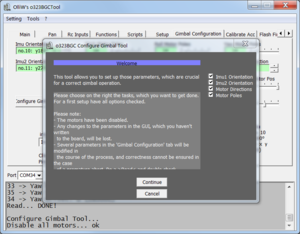
# In the welcome screen you can select what to configure, we want to do all and hence click on {{GUI|Continue}}. [[File:Gimbal config tool 2.png|none|300px]] | # In the welcome screen you can select what to configure, we want to do all and hence click on {{GUI|Continue}}. [[File:Gimbal config tool 2.png|none|300px]] | ||
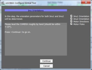
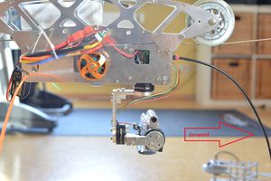
# Next we are asked to position the gimbal to look forward. So you manually adjust the camera so that it points into the forward direction of your copter. You might not be able to do that perfectly because of the motor magnets, 15° is more than enough. Once the camera is in forward position click on {{GUI|Continue}}. [[File:Gimbal config tool 3.png|none|300px]] [[File:|none|300px]] | # Next we are asked to position the gimbal to look forward. So you manually adjust the camera so that it points into the forward direction of your copter. You might not be able to do that perfectly because of the motor magnets, 15° is more than enough. Once the camera is in forward position click on {{GUI|Continue}}. [[File:Gimbal config tool 3.png|none|300px]] [[File:Gimbal config tool forward.jpg|none|300px]] | ||
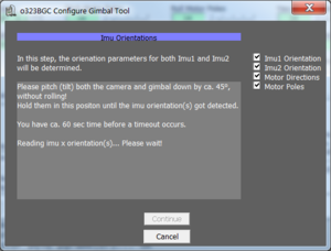
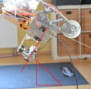
# Now you are asked to pitch the frame, the entire copter, by 45° downward, as if the goal would film the ground in front of the copter. So you lift the frame accordingly and both, frame and camera should point downwards. To be more precise, the camera should not move relative to the frame. If it does you should consider balancing the camera better. Anyway, the entire goal in this task is to get a clear reading of which axis of each IMU are all impacted by this 45° degree movement. The IMU does measure the accelarion values, as we are static its only acceleration is the earth gravity. For example the reading in the forward position might be x/y/z=0g/1g/0g. When pitching downward, the value could change to 0.7g/0.7g/0g and therefore we know that the pitch axis is along the z axis, its reading did not change (much). This plus the +/- sign allows to derive the IMU orientation by simply measuring it. [[File:Gimbal config tool 4a.png|none|300px]] [[File:|none|300px]] | # Now you are asked to pitch the frame, the entire copter, by 45° downward, as if the goal would film the ground in front of the copter. So you lift the frame accordingly and both, frame and camera should point downwards. To be more precise, the camera should not move relative to the frame. If it does you should consider balancing the camera better. Anyway, the entire goal in this task is to get a clear reading of which axis of each IMU are all impacted by this 45° degree movement. The IMU does measure the accelarion values, as we are static its only acceleration is the earth gravity. For example the reading in the forward position might be x/y/z=0g/1g/0g. When pitching downward, the value could change to 0.7g/0.7g/0g and therefore we know that the pitch axis is along the z axis, its reading did not change (much). This plus the +/- sign allows to derive the IMU orientation by simply measuring it. [[File:Gimbal config tool 4a.png|none|300px]] [[File:Gimbal config tool 45.jpg|none|300px]] | ||
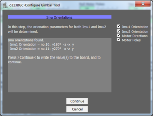
# Once the IMU orientation was read, the values are shown and we can continue with the next step. [[File:Gimbal config tool 4.png|none|300px]] | # Once the IMU orientation was read, the values are shown and we can continue with the next step. [[File:Gimbal config tool 4.png|none|300px]] | ||
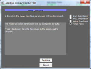
# This is just informational that the motor direction values are all being set to Auto. [[File:Gimbal config tool 5.png|none|300px]] | # This is just informational that the motor direction values are all being set to Auto. [[File:Gimbal config tool 5.png|none|300px]] | ||
Revision as of 20:43, 14 December 2014
Comment by OlliW: Werner, great that you're working on this here!! Unfortunately, the Gimbal Configuration Toll has changed dramatically with v0.57e.
You have a Gimbal, the StorM32-BGC board, the IMU and all cables. So what is next? This page is intended to guide you through the essential steps (based on the 0.56 firmware version) and contains references to the detail pages in case you need to know more. Basically the steps are
Ordering information
The StorM32-BGC board can be found at various shops. As of today there are three hardware revisions but frankly, they do not differ much. Hence nothing wrong with buying a v1.1 board, just keep in mind that some pins are placed at different places. Since the v1.3 hardware revision is the one you get everywhere these days, this page is using it as example. Together with the board buy an IMU and matching cable from the same vendor. There are tons of IMUs available but the connectors can be different. The plug on the StorM board is a so called Picoblade connector. And finally an USB-to-serial adapter with a matching cable is required for flashing the latest firmware. It can be any FTDI, CP2102, ..., but NOT a PL2303 based adapter. Again, if you do not have one already, I recommend getting this with the other parts. Personally I prefer those where the drivers come from the Windows Update Site automatically.
Things to watch out for when comparing prices
- Bluetooth module included? The StorM board is designed to solder an HC06 bluetooth module on it. Then you can run the config tool on your laptop via bluetooth. The range of these modules is quite low, so do not expect to use it to remote monitor the gimbal values in flight. If in future there will be a smartphone app available, this might be realyl cool for changing configurations, on the other hand, how often will you be doing that?
- Connectors soldered on it? Having connectors already soldered allows to simply plug in the motors and go. On the other hand, the RC and motor connectors are quite large, hence might be placed on the opposite side or motor cables being soldered directly to the board. Consider your preferences before buying.
- IMU and cable included already? Or does it come without the IMU?
Flash Firmware
Because the StorM board has a very active community, new firmware versions with new enhancements are released on about monthly basis these days, so the first step will be to flash the newest firmware. This description here assumes the board used was bought by a vendor with a firmware already uploaded and it should be updated only. Else refer to the How to flash firmware page. Very quickly, there are three typical traps when flashing
- The board has no power
- The pins labeled UART is used for flashing instead of the RC labeled pins
- Wrong serial port is selected in the tool
In order to flash a new firmware the following steps are recommended.
- Get your USB-to-serial adapter to work by installing all windows drivers as requested by the vendor.
- Unplug(!) the USB-to-serial adapter again
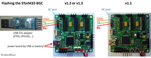
- Connect the USB-to-serial adapter to the StorM board to the pins labeled RC(!). The firmware is not programmed via the UART labeled port, not via USB but via the RC pins. In other words, when the board is brought into the bootload mode, the RC pins are re-assigned to microcontroller's UART1, in normal mode these pins are assigned to the PWM timer. And the pins labeled as UART are the mcu's UART0. All of this is a security measure to avoid people programming the board via e.g. bluetooth and end up with an nonoperational board.
- Connect the StorM board via USB to the computer. We are not using this connection yet but we power the board via USB. Although we do not need it yet, this might trigger Windows to install a driver for the STM processor's USB connection.
- Download the newest firmware, unzip it and run the exe file, in this example the o323BGCTool_v056.exe program. It does not matter what the current firmware installed is, you use the tool that comes with the firmware zip file. Get the zip file from here: Downloads.
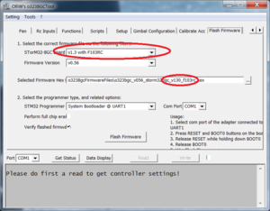
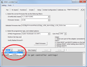
- In the tool select the [Flash Firmware tab] on the very right hand side and select the hardware revision of your board. This does change the firmware file to be used in the field below.
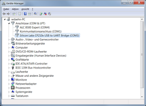
- In step two, the middle of the screen, there is a [com port selector] for flashing. NOT the com port selector at the bottom! Click on the drop down box to see all currently available com ports. Since we do not have connected the USB-to-serial adapter to the computer yet, the new one appearing when plugging in the adapter will be the one to use. Hence remember that list of ports to identify the new one in the next step.
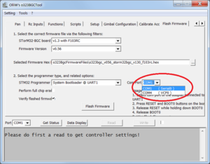
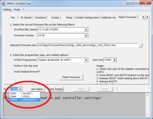
- Plugin the USB-to-serial adapter and click again on the drop down box of the serial connector for programming. Select the new one.
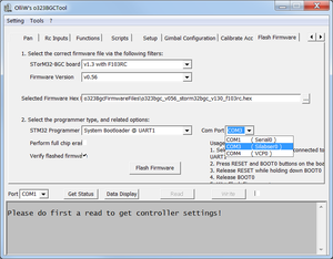
- The board has two buttons, the boot and reset button. When the board is started, the very first thing the software does is checking if the boot button is currently pressed. If it is, the bootloader mode is entered, else the normal operation starts. The best way of entering the bootloader mode is hence to press the boot button and while it is pressed press and release the reset button to initiate a hard reset.
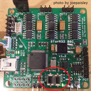
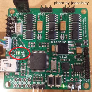
- Check if the board is in bootloader mode or in operational mode. If the boards appears to be dead, then it is brought into bootloader mode successfully, if the Leds are blinking, it is in normal operation and obviously the boot button was not pressed while the reset button was released.
- Now the board is listening on the RC pins for serial data, the usb adapter is connected, the firmware tool is using the Windows COM port of the serial adapter, hence you can click on [Flash Firmware] button.
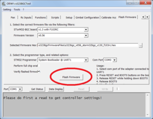
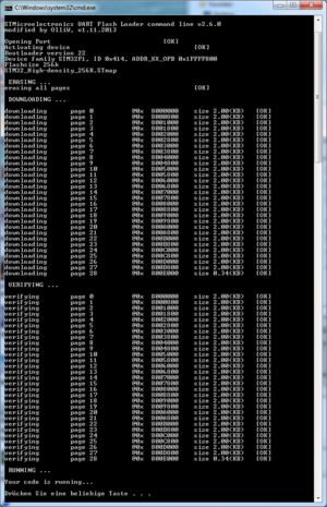
- A dos box will open and either return an error that the UART connection is not responding or a sequence of downloading and verifying the firmware is shown.
- After the reset your board is operational and can be reached via the USB cable. Hence disconnect both, the USB cable and the USB-to-serial adapter and click on the com port selector at the very bottom. Again, remember the list.
- Then plugin the StorM board via the USB cable to power it. Either the matching driver was installed already or it will be installed now. Either way once windows has installed the driver when clicking on the drop down for the com port selector, it should now show an additional one.
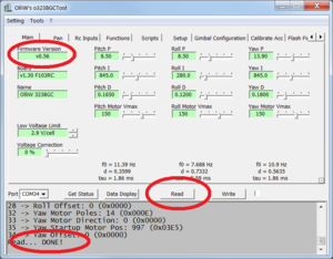
- Jump back to the [Main tab] and click on [Read] to validate the connection with the board.


In case you have troubles with the StorM's USB driver, it can be found here: download page.
Hardware setup
The camera IMU
This IMU is to be mounted in a way so that it does measure all camera movements. Its actual position does not matter, behind the camera, on the pitch arm below the camera,... anything will work. The only thing to watch out for is that its axis are aligned with the camera axis. Each axis has to be either horizontal or vertical. Just imagine, the sensor would read that the horizon is level but because of an misalignment the camera does hang slightly to one side and hence the horizon in the video is not level.
Mounting the StorM board
One of the outstanding features of the StorM board is its 2nd IMU support. In fact the board has such IMU itself already and to make use of it, the board should hence be mounted on the copter frame. The direction does not matter as long as it is the frame. In case this is not possible, either the 2nd IMU support has to be disabled or another external IMU is mounted to the frame and connected to the frame I2C connector. Again, the IMU axis have to be either vertical or horizontal.
Electric connection and insulation
All the IMUs go to their corresponding I2C plug, that is the I2C labeled Picoblade connector next to the USB connector for the camera IMU.

On the backside of the board is a I2C#2 connector for the optional frame IMU.
One thing we found out the hard way is to never mount the board or the IMUs with metal screws and distance sleeves, always use plastic ones. Not only does that enhance the probability of survival in case of an electric defect but also the I2C bus might use the entire metal frame and motors as antenna. Which leads to massive amounts of errors on the I2C bus. And without constant readings of the IMU positions the entire purpose of the gimbal is forfeit. Make sure the IMUs are mounted rigidly also so they measure the actual position.
Gimbal mechanics
Before using the gimbal, it is absolutely necessary to balance it and to ensure minimum resistance to rotations (friction in bearings, stiff cables, etc). Any improper balance or resistance to rotation will make setting up the gimbal more difficult or even impossible. The goal shall be to rotate the camera in the gimbal and it should stay in that position by itself. In other words, the center of gravity should be in the center of all gimbal motor axis. Just imagine the camera's center of gravity is way below the pitch axis (looking with the camera up and down). It would act like a pendulum. So just because your copter does accelerate forward, the gimbal pitch motor has to hold against the mass inertia. You will need very strong motors and lots of energy which is a waste. On the other hand, if the gimbal is balanced properly, all the motor has to compensate is copter rotations, wind resistance and inertia when rotating the camera to point to somewhere else.
Powering the Gimbal
For the motors the 5V supply of the USB bus is not enough for sure. So the motors will work only if the battery connector provides the power. That is the reason why e.g. flashing the firmware is done via USB power only as we do not want to motors to get power at that time. The battery connector can handle any voltage from 6V to 18V. Connecting the PC via the USB cable while the board is powered via a battery is no problem at all. The order does not matter, first USB then battery or reverse, both will work.
Motor connector
The board has three connectors for the motors labeled Mot0 to Mot2. Before connecting any motor, it might be a good idea to measure the resistance of the motor windings and the motor frame. The three motor cables should have an electrical resistance of 12 Ohm or more and completely isolated from the motor housing. If the resistance is too low, the amount of amps flowing through the motor might be too high for the board driver to handle. And if one of the motor cables is connected to the motor housing, the entire gimbal and maybe even the frame gets the motor voltage. The usage of the three connectors is
- Mot0: Pitch motor to point the camera up/down
- Mot1: Roll motor to stabilize the horizon
- Mot2: Yaw motor to turn the camera left/right
Summary
Motors are connected, IMU(s) are connected, battery power cable is ready and its polarity doublechecked.

First Configuration
The last steps in the firmware flashing section had been to check if the StorM32-BGC is operational.
- Disconnect the USB cable and click on the com port selector at the very bottom. Remember the list.
- Plugin the StorM board via the USB cable to power it. Either the matching driver was installed already or it will be installed now. Either way once windows has installed the driver when clicking on the drop down for the com port selector, it should now show an additional one.
- Jump back to the [Main tab] and click on [Read] to validate the connection with the board.
Now it's time to set the most important parameters, namely the IMU orientations and motor parameter values. Without that the controller can't perform the basic operations even. With the Gimbal Configuration tool this is very simple.
- Change to the [Gimbal Configuration tab]. There you can enter the values for the motor poles, the motor directions and the IMU orientation manually, or run the [Configure Gimbal Tool].
- In the welcome screen you can select what to configure, we want to do all and hence click on [Continue].
- Next we are asked to position the gimbal to look forward. So you manually adjust the camera so that it points into the forward direction of your copter. You might not be able to do that perfectly because of the motor magnets, 15° is more than enough. Once the camera is in forward position click on [Continue].
- Now you are asked to pitch the frame, the entire copter, by 45° downward, as if the goal would film the ground in front of the copter. So you lift the frame accordingly and both, frame and camera should point downwards. To be more precise, the camera should not move relative to the frame. If it does you should consider balancing the camera better. Anyway, the entire goal in this task is to get a clear reading of which axis of each IMU are all impacted by this 45° degree movement. The IMU does measure the accelarion values, as we are static its only acceleration is the earth gravity. For example the reading in the forward position might be x/y/z=0g/1g/0g. When pitching downward, the value could change to 0.7g/0.7g/0g and therefore we know that the pitch axis is along the z axis, its reading did not change (much). This plus the +/- sign allows to derive the IMU orientation by simply measuring it.
- Once the IMU orientation was read, the values are shown and we can continue with the next step.
- This is just informational that the motor direction values are all being set to Auto.
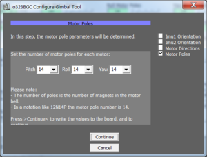
- Last step is the motor pole counts for each motor. This is again information you should get from the motor vendor, data like N12P14, meaning 14 poles.
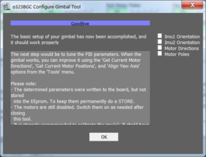
- With this the basic parameters are set but not stored permanently in the board. So you click on [Okay] to close the wizard.
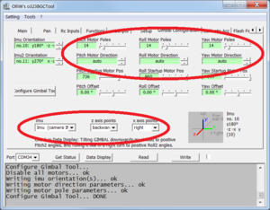
- The setup screen got updated now with the provided IMU, IMU2 and motor pole counts for each motor. All motors are disabled and the direction set to Auto.
- In order to make these settings permanently stored, tick the checkbox next the [Write] button and the button will change its label to [Write+Store]. Press that button and the values get saved in the board's eeprom.
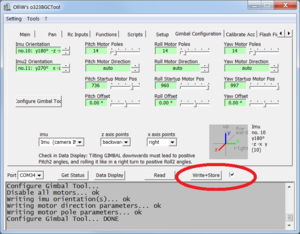
- Attention: These values are used at startup only. Hence you have to reset the board!


First Startup
With above steps completed, plug in the battery in order to get power to the motors. Remember, the motor outputs had been disabled in above step. Now position the camera to look forward by hand and then enable the motors. In the [Setup] tab check that the [Pitch Usage], [Roll Usage] and [Yaw Usage] parameter fields, they are all set to "disabled". Change them to "normal" individually. Or better, click on [Enable all Motors]), and write and store the changed setting. Without the writing the values all you did is changing the values on your computer. Without the store the changes are not saved permanently in the controller's eeprom.
The controller will now go through a sequence of steps. settle - calibrate - level - autodir - relevel - normal
- Settle: In order to calibrate to normal, the gimbal has to be stable, it should not be moved. In a copter that is quite simple as the copter is on the ground, a handheld device needs to be put at a table to remain in one position for a few seconds.
- Calibrate: Calibrate the sensors. Take a second at max.
- Level: This is the point where the motors will be turned in order to level the camera in pitch and roll axis. Yaw motor is under power, so you feel some resistance but does not move yet.
- Autodir: Here the motors are moved slightly into one direction and based on the sensor changes the controller knows if this was an up or down etc movement and will use this as the motor directions.
- Relevel: Since autodir did move the camera, it is quickly brought back in a horizontal position.
- Normal: The is the final stage and now the gimbal is operational. Simply move the camera out of position by hand, move the frame,... whatever you do the camera should remain stable. You can pitch the camera+-90°, you can yaw the camera by +-180° or roll the camera about +-45°. More roll is not possible as then the pitch axis and the yaw axis get more and more aligned. In a roll of 90° the pitch and yaw axis would both rotate the camera.
In the past the first startup was problematic often and after lots of debugging the same root causes were identified: Motor directions, IMU orientation and occasionally the motor pole count. Therefore the Gimbal Configuration tool was implemented and hence all of these problems should be gone.
- During the level phase the gimbal does constantly move around, never finding the level position: The Pitch and Roll Motors are not connected to Mot0 (Pitch) and Mot1 (Roll) but reverse. Hence the control logic does measure that pitch has to be changed by -5°, applies the proper movement sequence to the motor but all that happens is that suddenly the roll value is off by -5°. Make sure the motors are connected correctly.
- Camera turns upside down or things like that: The IMU orientation is wrong.
- Gimbal starts shaking, makes high frequency noises and things like that: This would be normal as we have not configured the PID values for the motor control loop yet. In case that happens, set for all motors the P, I and D values to very low numbers but not zero (P=0.10; I=5.0; D=0.0050) and write them to the board. This will cause the gimbal to be slow when correcting movements but at least you can prove all is functional.
We can save some time during the startup if we would speedup the levelling and the motor directions. For this we have three options in the [Tools] menu.

- [Get Current Motor Directions]: Since the gimbal is now in a normal operation, the Autodir phase was completed, it knows the directions. By selecting this menu the motor directions in the [Gimbal Configuration] tab are changed from "auto" to their actual direction "normal" or "reverse".
- [Get Current Pitch and Roll Motor Positions]: Initially the gimbal does not know the current motor position. So it powers the motor's windings to assume a default position. Now that the gimbal is level, we know the motor positions default. Hence we can take the current position as "Pitch Startup Motor Pos" and "Roll Startup Motor Pos"
- [Adjust Yaw Startup Motor Pos Parameter Tool]: Yaw is a different story. The current Yaw value cannot be zero'ed in as there is no sensor telling what "forward" means. Hence the motor start position is the only way but using what value? With the Yaw tool you can manually move the gimbal in yaw to bring it into the forward position and then safe that as the "Yaw Startup Motor Pos".
Don't forget to [Write+Store] these values permanently by ticking the checkbox next to the [Write] button to change its label and click that button.
Next step - PID Tuning
At this point the gimbal may already stabilize the camera. However, usually, the camera is not yet stabilized perfectly, or the gimbal may even start to show weird shaking or make high frequency noises. This indicates that the PID values in the [Main] tab are not proper.
See the PID parameter Tuning Guide for adjusting those.