Getting Started: Difference between revisions
mNo edit summary |
|||
| (227 intermediate revisions by 4 users not shown) | |||
| Line 1: | Line 1: | ||
<span style="font-size:88%">''by Yang/wdaehn and OlliW, with videos by alcurtis93, descriptions refer to firmware v0.67e</span>'' | |||
You have a gimbal, the STorM32-BGC board, the IMU module and all cables. So what is next? This page is intended to guide you through the essential steps, and provides references to more specific pages in case you need to know more. Basically the steps are: | |||
<div class="toclimit-2">__TOC__</div> | |||
== | == Ordering Information == | ||
Things to order at minimum: | |||
* STorM32-BGC board | |||
* IMU module and matching cable | |||
* USB-to-serial adapter | |||
The STorM32-BGC board can be obtained from various shops. There are several hardware revisions around, but, frankly, they do not differ much. A v1.3 board is used exemplary below. | |||
Together with the board, buy also an IMU module and a matching cable from the same vendor. There are tons of different IMU modules available, and different connectors are in use. The plug on the STorM32 board is a so-called [http://www.molex.com/molex/products/family?key=picoblade&channel=products&chanName=family&pageTitle=Introduction Picoblade] connector (often, but incorrectly, called JST 1.25 connector). | |||
Finally, a USB-to-serial adapter with a matching cable is required for flashing the latest firmware. It can be any USB-to-serial adapter with FTDI or CP2102 or CH340 chips (also known as USB-TTL adapters), but NOT a PL2303-based adapter (for details please see | |||
[[STorM32_FAQ#Which USB-TTL should I use.3F|FAQ: Which USB-TTL should I use?]]). If you do not have one already, buy one together with the other parts. Note: If you're planing to use STorM32 NT modules, then get a USB adapter with FTDI chip (see [[Updating the Firmware of NT Modules|here]]). | |||
Things to watch out when comparing prices | |||
* Bluetooth module included? Most STorM32 boards are designed for a HC06 Bluetooth module to be soldered on it. Then you can run the GUI on your laptop via Bluetooth. The range of these modules is modest, so do not expect that it allows to remotely monitor the gimbal values in flight. If in future a smartphone app should become available, this might be really cool for changing configurations, on the other hand, how often will you be doing that? | |||
* Connectors soldered to it? Preinstalled connectors allow to simply plug in the motors and go. On the other hand, the RC and motor connectors are quite large, hence you may wish to place them differently or to solder motor cables directly to the board. Consider your preferences before buying. | |||
* IMU module and cable included? Is the IMU cable soft enough and of appropriate length? | |||
'''Related wiki articles:''' | |||
* [[Where to buy STorM32 boards]] | |||
* [[Boards]] | |||
* [[STorM32_FAQ#What_are_the_differences_between_the_boards.3F|FAQ: What are the differences between the boards?]] | |||
* [[STorM32_FAQ#Will_my_motors_work_with_my_STorM32_board.3F|FAQ: Will my motors work with my STorM32 board?]] | |||
* [[STorM32_FAQ#Which USB-TTL should I use.3F|FAQ: Which USB-TTL should I use?]] | |||
== Dos and Don'ts == | |||
{{WARNING|Read and comprehend the [[Dos and Don'ts]].}} | |||
== Supported Gimbals == | |||
The STorM32 controller supports several setups, see [[Quick_Start_Guide#Supported_Gimbals|Supported Gimbals]]. | |||
== Flashing Firmware == | |||
The STorM32 board has a very active community, and new firmware versions with new enhancements are released on about a monthly basis. So, the first step will be to flash the newest firmware. | |||
Your board may come or may not come with a firmware loaded; this depends on the vendor. In the first case you could skip the following steps and just install the GUI, but it is recommended to carry them out nevertheless, in order to get the latest firmware and GUI. In the latter case you must go through the steps; without firmware the board obviously would not function. The following description applies to both cases, only the USB driver gets installed by Win 7 in different steps; see the red warnings. It is crucial to NOT interrupt the USB driver install process. It can take several minutes, so please be patient. | |||
In order to flash a new firmware the following steps are recommended. | |||
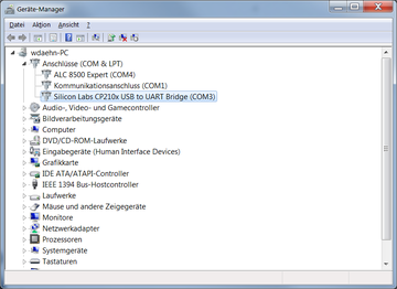
# Get your USB-to-serial adapter to work by installing all Windows drivers as requested by the vendor. [[File:Usb-to-uart-driver.png|none|360px]] | |||
# Unplug (!) the USB-to-serial adapter again. | |||
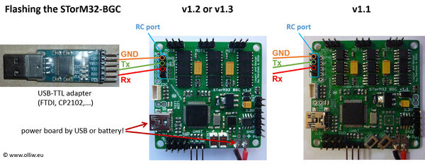
# Connect the USB-to-serial adapter to the STorM32 board at the pins labeled RC (!). The firmware is '''NOT''' programmed via the UART port, '''NOT''' via the USB, but via the RC pins. In other words, when the board is put into bootloader mode, the RC pins are re-assigned to the microcontroller's UART1 as needed for flashing the firmware; normally they are assigned to the PWM timers. [[File:Stom32-bgc-flashing-w-usbttladapter-connections-02.jpg|none|600px]] | |||
# Connect the STorM32 board via USB to the computer. We are not using this connection yet, but we power the board via USB.<br>{{WARNING|If the board has already a firmware installed and this is the first-time connection to your PC, then Windows will install the USB driver for the STorM32 board. This can take quite some time. Do '''NOT''' interrupt the install process.}} | |||
# Download the newest firmware, unzip it and run the GUI, in this example the o323BGCTool_v067e.exe program. It does not matter what the currently installed firmware is, you use the GUI that comes with the firmware zip file. Get the zip file from here: [[Downloads]]. | |||
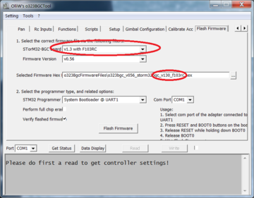
# In the GUI select the {{GUI|Flash Firmware}} tab on the very right hand side and select the hardware revision of your board. This does change the firmware file to be used in the field below. [[File:Firmware_selector.png|none|360px]] | |||
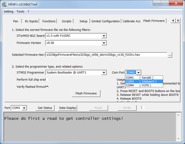
# Now select the COM port of the USB-to-serial adapter. This is done with the {{GUI|Com Port}} selector in the middle of the screen, NOT the com port selector at the bottom! Click on the drop down box to see all currently available COM ports. Since we do not have connected the USB-to-serial adapter to the computer yet, the new one appearing when plugging in the adapter will be the one to use. Hence remember that list of ports to identify the new one in the next step. [[File:Firmware_comport1.png|none|360px]] | |||
# Plugin the USB-to-serial adapter and click again on the drop down box of the serial connector for programming. Select the new one. [[File:Firmware_comport2.png|none|360px]] | |||
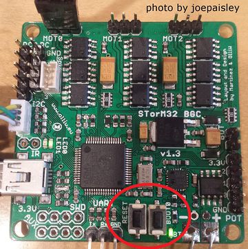
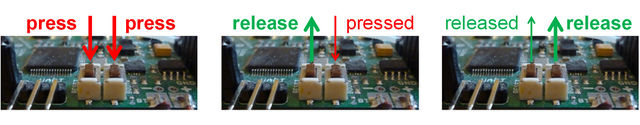
# The board has two buttons, the boot and reset button. When the board is started, the very first thing the firmware does is checking if the boot button is currently pressed. If it is, then the bootloader mode is entered, else the normal operation starts. The best way of entering the bootloader mode is hence to press the boot button and while it is pressed to press and release the reset button to initiate a hard reset. [[File:Firmware-bootloadermode.jpg|none|360px]] [[File:Storm32-wiki-flash-firmware-key-sequence-01.jpg|640px]] | |||
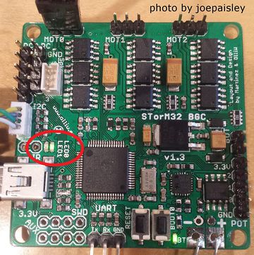
# Check if the board is in bootloader mode. When the board appears to be dead (green and red LEDs off, the yellow LED is irrelevant), then it is brought into bootloader mode successfully, if the green and red LEDs are blinking, it is in normal operation and obviously the boot button was not pressed while the reset button was released. [[File:Firmware-bootloadermode-leds.jpg|none|360px]] | |||
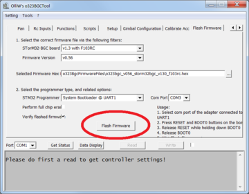
# Now the board is listening on the RC pins for serial data, the USB-to-serial adapter is connected, and the correct COM port of the adapter is selected, so you can click on the {{GUI|Flash Firmware}} button. [[File:Firmware_start_flash.png|none|360px]] | |||
# A black DOS box will open and either return an error that the UART connection is not responding or a sequence of downloading and verifying the firmware is shown.<br>{{WARNING|If this is a first-time flash of a "virgin" board, then Windows will start with installing the USB driver directly after the flash has finished. This can take quite some time. Do '''NOT''' interrupt the install process.}} [[File:Flash.png|none|360px]] | |||
# After the reset, your board is fully operational and you may disconnect the USB-to-serial adapter. | |||
The process is also nicely described in this video by rcgroups user alcurtis93: | |||
{{#ev:youtube|HwaHjRw1Qqg}} | |||
'''Quick Trouble Shooting:''' | |||
* It is '''''strongly''''' recommended to also read the [[How to flash firmware]] page for trouble shooting. | |||
* The board has no power - connect the board to the computer via USB to power it. | |||
* The pins labeled UART are used for flashing - which is wrong, the RC pins should be used. | |||
* Wrong serial port is selected in the tool. | |||
* The black DOS box doesn't show up, e.g. because the firmware .zip file was not extracted. | |||
* The above steps run though and the black DOS box shows the first two [OK] messages, but the downloading and verifying message lines are not be present and a firmware is not flashed. Some few boards are shipped with enabled read&write protection of the flash, which causes the issue. Go to [[How to flash firmware#Removing Read&Write Protections|Removing Read&Write Protections]]. | |||
* In case of troubles with the USB driver, consult the [[STorM32_FAQ#Which_drivers_are_needed_for_the_USB.3F|FAQ: Which drivers are needed for the USB?]]. | |||
'''Related wiki articles:''' | |||
* [[How to flash firmware]] | |||
* [[STorM32_FAQ#Which_drivers_are_needed_for_the_USB.3F|FAQ: Which drivers are needed for the USB]] | |||
== Checking Connection to the GUI == | |||
Let's next check if the STorM32-BGC is indeed operational, and communicates with the GUI. Note that firmware and GUI versions must match. | |||
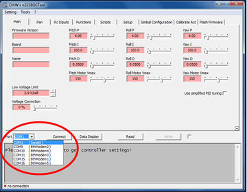
# If connected, disconnect a USB cable and/or USB-to-serial adapter. Click on the COM port selector in the left bottom and memorize the list. [[File:Storm32-wiki-b-1-01.jpg|none|360px]] | |||
# Then plug in the STorM32 board via the USB cable to power it. When clicking on the drop down for the COM port selector, it should now show an additional one.<br> {{WARNING|If the board has a firmware installed and this is the first-time connection via USB to your PC, then Windows will install the USB driver for the STorM32 board. This can take quite some time. Do '''NOT''' interrupt the install process.}} [[File:Storm32-wiki-b-2-01.jpg|none|360px]] | |||
# Go to e.g. the {{GUI|Main}} tab and click on {{GUI|Connect}} or {{GUI|Read}} to validate the connection with the board. [[File:Storm32-wiki-b-3-01.jpg|none|360px]] | |||
It's a good occasion now to also learn about the {{GUI|Read}}, {{GUI|Write}} and {{GUI|Write+Store}} buttons and to read [[STorM32_FAQ#How_does_Read.2C_Write.2C_and_Store_work.3F|FAQ: How does Read, Write, and Store work?]]. | |||
'''Quick Trouble Shooting:''' | |||
* Wrong COM port selected. | |||
* Firmware and GUI version numbers do not agree. | |||
[[ | '''Related wiki articles:''' | ||
* [[STorM32_FAQ#Which_drivers_are_needed_for_the_USB.3F|FAQ: Which drivers are needed for the USB?]] | |||
* [[STorM32_FAQ#How_does_Read.2C_Write.2C_and_Store_work.3F|FAQ: How does Read, Write, and Store work?]] | |||
* [[STorM32_FAQ#How_to_enter_precise_parameter_values.3F|FAQ: How to enter precise parameter values?]] | |||
== Hardware Setup == | |||
=== The Camera IMU === | |||
The camera IMU needs to be mounted such that it measures all camera movements. Its actual position does not matter, behind the camera, on the pitch arm, below the camera,... anything will work. The only thing to watch out for is that its axes are aligned with the camera axes. Each axis has to be either horizontal or vertical. Just imagine that the sensor would measure that the horizon is level but because of a misalignment the camera does hang slightly to one side and hence the horizon in the video is not level. | |||
[[ | A typical beginners mistake is to route the IMU cables in close proximity to the motor cables. This may however lead to I2C errors, and subsequent artifacts such as a "freezing" of the gimbal. If in doubt, please check the web, it is full of discussions on this topic, and/or consult the [[I2C Error Compendium]]. BTW, the STorM32 NT concept offers an ultimate solution to this issue by abandoning the I2C bus altogether (for more info see [http://www.rcgroups.com/forums/showthread.php?t=2434504 STorM32-NT BGC]). | ||
<!-- | |||
Another important note. Some people are reporting that the gimbal freeze in one position some time after power on. This most likely is due to signal interference on from the motor cables. In order to avoid this problem, make sure the IMU cable is not routed the same way as the cable to the motor(s). It is of course very tempting to place the IMU close to the pitch motor and then pull the IMU cable together with the pitch motor cable in order to have as clean cabling as possible. This "may" work, but if the gimbal freezes in one position after some time, the interference from the motor cable to the I2C cable (IMU cable) is most likely the cause of the problem. To test this, just route the IMU cable as far away from the motor cable as possible. If this does not help, try moving also the IMU as far away from the motors and motor cables as possible too. | |||
Another solution is to add ferrite ring on the IMU cable. Read the [http://www.olliw.eu/storm32bgc-wiki/I2C_Error_Compendium details of I2C errors] for technical explanation of the problem. | |||
--> | |||
== | === Mounting the STorM32 Board === | ||
One of the outstanding features of the STorM32 board is its 2nd IMU support. In fact the board has such an IMU on-board already. To make use of it, the board needs to be mounted such that it measures the movements of the copter frame. The direction does not matter as long as it measures the frame's movements. In case this is not possible, either the 2nd IMU support has to be disabled, or another external IMU can be mounted to the frame and connected to the frame I2C connector, labeled I2C#2. As for the camera IMU, also the axes of the 2nd IMU have to be vertical or horizontal, respectively. | |||
Related wiki articles: | |||
* [[Using a 2nd IMU]] | |||
=== Electric Connection and Insulation === | |||
The | The IMUs go to their corresponding I2C plugs: The camera IMU goes to the picoblade connector labeled I2C next to the USB connector. On the backside of the board is the I2C#2 connector for the optional frame IMU. {{WARNING|The camera IMU must go to the port I2C, near the USB plug!}} Your board may have been shipped with a IMU pre-connected to port I2C#2, which is incorrect. | ||
[[File:Stom32-bgc-v130-ports-and-connections-01.jpg|none|600px]] | |||
One thing we found out the hard way is to never mount the board or the IMUs with metal screws and/or metal distance sleeves. Always use plastic ones. Not only does this help to avoid electrical problems but also the I2C bus can be sensitive to the nearby metal parts, leading to massive error rates on the I2C bus. Without a continuous readings of the IMU positions the entire purpose of the gimbal is forfeit. | |||
Make also sure that the IMUs are mounted rigidly, so that they measure the actual position. | |||
Related wiki articles: | |||
* [[Dos and Don'ts]] | |||
* [[Pins and Connectors]] | |||
* [[I2C Error Compendium]] | |||
=== Gimbal Mechanics === | |||
Before using a gimbal, it is absolutely necessary to balance it and to ensure minimum resistance to rotations (friction in bearings, stiff cables, etc). Any improper balance or resistance to rotation will make setting up the gimbal more difficult or even impossible. The goal shall be to rotate the camera in the gimbal and it should stay in that position by itself. In other words, the center of gravity should be in the center of all gimbal motor axes. Just imagine the camera's center of gravity is way below the pitch axis (looking with the camera up and down). It would act like a pendulum. So just because your copter does accelerate forward, the gimbal pitch motor has to hold against the mass inertia. You will need very strong motors and lots of energy which is a waste. On the other hand, if the gimbal is balanced properly, the motor only has to compensate the copter rotations, wind resistance and inertia when rotating the camera to point to somewhere else. | |||
Related wiki articles: | |||
* [[Tuning_Recipe#Balancing_the_Gimbal|Balancing the Gimbal]] | |||
=== Powering the Gimbal === | |||
For the motors the 5 V supply of the USB bus is too low. So, the motors will work only if a battery with sufficient voltage is connected. That is the reason why e.g. flashing the firmware is done using USB power only, as we do not want the motors to get power in that case. The battery connector can handle any voltage from 6 V to 18 V. Connecting the PC via the USB cable while the board is powered via a battery is no problem at all. The order does not matter, first USB then battery, or vice versa, both will work. | |||
=== Motor Connectors === | |||
The board has three connectors for the motors labeled Mot0, Mot1 and Mot2. Before connecting any motor, it is a good idea to measure the resistance of the motor windings and the motor frame. The three motor cables should have an electrical resistance of 12 Ohm or more and be completely isolated from the motor housing. If the resistance is too low, the amount of amps flowing through the motor might be too high for the board driver. If one of the motor cables has a short to the motor housing, the entire gimbal and maybe even the frame gets the motor voltage. | |||
The usage of the three connectors is | |||
* Mot0: Pitch motor to point the camera up/down | |||
* Mot1: Roll motor to stabilize the horizon | |||
* Mot2: Yaw motor to turn the camera left/right | |||
The motors need to be connected in this order to the motor ports. The three wires of a motor in contrast can be connected to its port in any order, here the order does not matter. | |||
=== Summary === | |||
Now the motors are connected, the IMU(s) are connected, the battery power cable is ready, and its polarity double-checked. | |||
[[File:Storm32-wiki-a-1-02.jpg|none|480px]] | |||
== Basic Controller Configuration == | |||
Now it's time to set the most important parameters, namely the IMU orientations and motor parameter values, which are located on the {{GUI|Gimbal Configuration}} tab. Without that, the controller can't do even the most basic operations. Setting these parameters correctly by hand is difficult, however, the GUI provides the {{GUI|Configure Gimbal Tool}}, which makes that very simple. | |||
You should be prepared to know the number of poles of your motors, as well as be ready to connect a battery on demand (if you haven't already plugged in a battery). | |||
{{WARNING|In the following the gimbal '''MUST''' be at rest and '''NOT''' be moved at all times (unless you're specifically asked to do differently).}} Ergo, don't hold the gimbal in your hands. {{WARNING|Also, a camera '''MUST''' be installed in the gimbal.}} Without camera gimbals don't work properly. | |||
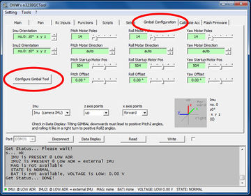
# Change to the {{GUI|Gimbal Configuration}} tab. There you find the parameter fields for the IMU orientations, motor poles, motor directions and motor startup positions. To set them, run the {{GUI|Configure Gimbal Tool}}. [[File:Storm32-wiki-c-1-01.jpg|none|360px]] | |||
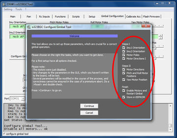
# In the welcome screen you can select what to configure. The individual steps are grouped into '''Steps I''' and '''Steps II''', and some finishing steps. You want to do all, and hence just click on {{GUI|Continue}}. [[File:Storm32-wiki-c-2-01.jpg|none|360px]] | |||
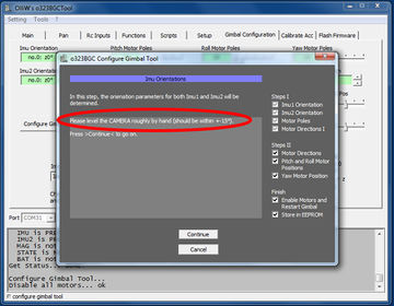
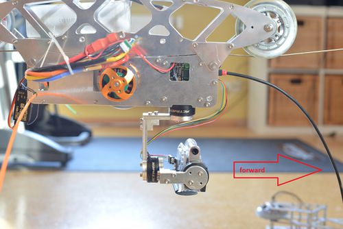
# You are now asked to position the gimbal and camera. The gimbal should be in its standard default position. Adjust the camera manually such that it is level and points into the forward direction of your copter. You might not be able to do that perfectly because of the motor magnets, but you should get that better than to within 15°. Once the camera is in forward position click on {{GUI|Continue}}. [[File:Storm32-wiki-c-3-01.jpg|none|360px]] [[File:Gimbal config tool forward.jpg| none | 500px]] | |||
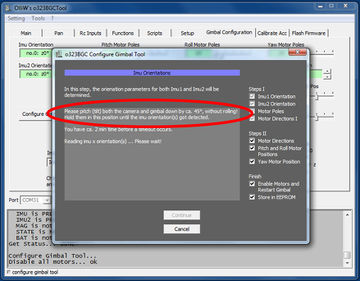
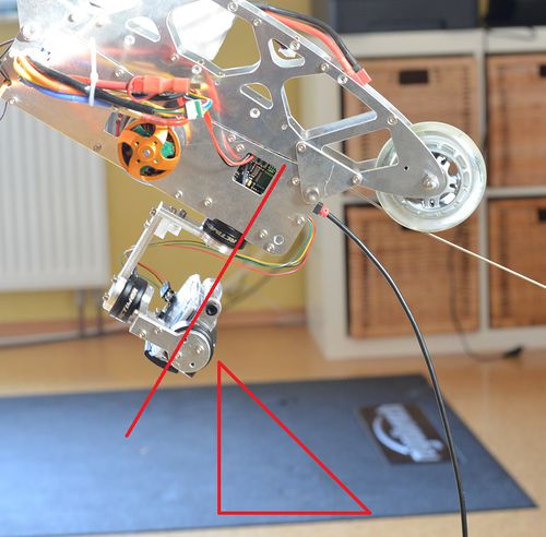
# Now you are asked to pitch the entire frame inclusive camera downwards by 45°, as if you would want to film the ground in front of the copter. So you lift the frame such that both, frame and camera, point downwards. Importantly, the camera should not move and keep its position relative to the frame. If it does move then you should consider balancing the camera better. Also, avoid roll movements. Anyway, the goal in this step is to measure the effect of a downturn by 45° degree on the IMU's signals. The IMUs do measure the acceleration values, and as we are static its the earth gravity. For example, the reading in normal position might be x/y/z = 0 g/1 g/0 g. When pitching downwards, the values may change to 0.7 g/0.7 g/0 g, and from that we know the IMU's orientations. [[File:Storm32-wiki-c-4-01.jpg|none|360px]] [[File:Gimbal config tool 45.jpg| none | 500px]] | |||
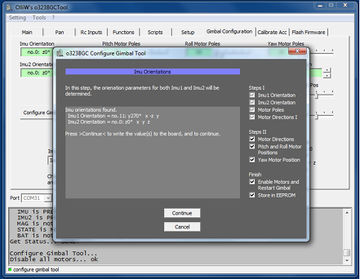
# Once the IMU orientations were determined, their values are shown and you can (should) put the gimbal back to normal position. When you can continue with the next step. [[File:Storm32-wiki-c-5-01.jpg|none|360px]] | |||
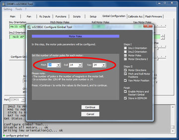
# The next important step is to set the motor pole counts for each motor. This is information you should get from the motor vendor. Data like N12P14 means 14 poles. [[File:Storm32-wiki-c-6-01.jpg|none|360px]] | |||
<!-- | |||
# We are now informed that all motor direction values will be set to {{PARAMVALUE|auto}}. [[File:Storm32-wiki-c-7-01.jpg|none|360px]]--> | |||
# On the next screen you are informed that all motor direction values will be set to {{PARAMVALUE|auto}}. Click {{GUI|Continue}}. | |||
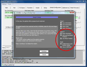
# This completes the settings of '''Steps I''', and you can proceed with adjusting the parameters of '''Steps II'''. [[File:Storm32-wiki-c-8-01.jpg|none|360px]] | |||
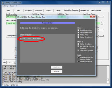
# For the next steps to work, the gimbal has to be started up with enabled motors, and a battery must be connected. The GUI will check for that, and will ask you to connect a battery if required. Do as advised. [[File:Storm32-wiki-c-9-01.jpg|none|360px]] | |||
# The gimbal will now go through it's initialization steps, which you can follow in the screen. Please wait until it reaches the NORMAL state. You should see the green LED go solid, as well as hear a beep. You are reminded to keep the gimbal in normal position and at rest during all this.<br>{{WARNING|If this step doesn't complete or an error occurs see the [[#Basic_Controller_Configuration_Quick_Trouble_Shooting|Quick Trouble Shooting]] section below, and please take any recommendations from there seriously.}} [[File:Storm32-wiki-c-10-01.jpg|none|360px]] | |||
<!-- | |||
# We are now informed that the motor direction values will be set for all motors. [[File:Storm32-wiki-c-11-01.jpg|none|300px]] | |||
--> | |||
# On the next screen you are informed that the motor direction values will be determined for all motors. Click {{GUI|Continue}}. | |||
<!--# We are now informed that the motor startup positions for the pitch and roll motors are set. [[File:Storm32-wiki-c-12-01.jpg|none|300px]] | |||
--> | |||
# In a further screen you are informed that the motor startup positions for the pitch and roll motors are determined. Click {{GUI|Continue}}. | |||
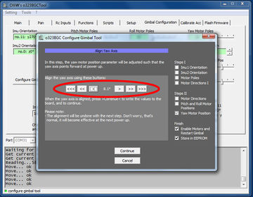
# Now you are asked for another important step, namely to align the camera such as to point forward. Use the buttons to turn the camera until you're satisfied. The goal of this step is to align the camera with the 2nd IMU. A precise alignment is required for the 2nd IMU function to work correctly. You don't have to overdo however, a visual accuracy of the alignment is sufficient. [[File:Storm32-wiki-c-13-01.jpg|none|360px]] | |||
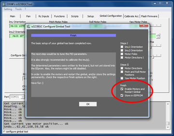
# This completes the settings of '''Steps II'''. What is left is to store all values in non-volatile memory, and to restart the gimbal. [[File:Storm32-wiki-c-14-01.jpg|none|360px]] | |||
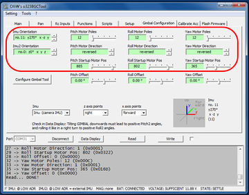
# The results of the above steps can be seen in the {{GUI|Gimbal Configuration}} tab, which got updated with the new IMU orientations and motor parameters. Also the motors are enabled, and the system is functional now. [[File:Storm32-wiki-c-16-01.jpg|none|360px]] | |||
<span id="Basic_Controller_Configuration_Quick_Trouble_Shooting">'''Quick Trouble Shooting:'''</span><br> | |||
It may happen that the tool gets stuck in step 10. This generally indicates a serious problem with the setup, and not the controller. Examples are: | |||
* Motors are not connected to the correct ports. | |||
* Motors are not working properly because of e.g. a broken wire or bad connection. | |||
* The IMU(s) do not work properly because they are connected to the wrong ports, or step 4 wasn't done correctly. | |||
* I2C errors occur because of inappropriate routing of motor and I2C cables (consult also the [[I2C Error Compendium]]). | |||
* PID parameters are totally wrong for the gimbal. | |||
* Read also the [[#First_Startup_Quick_Trouble_Shooting|Quick Trouble Shooting]] section in the next chapter! | |||
'''Related wiki article:''' | |||
* [[Quick Start Guide]] | |||
== First Startup == | |||
After the above steps were completed, the STorM32 controller was reset and hence will start up now. | |||
At startup, the controller goes through its initialization steps, which typically takes about 20 - 25 seconds. Note that the gimbal should not be moved until the initialization is finished and the controller has reached normal operation. This is indicated by greed LED going solid, and - if enabled - by a beep. | |||
'''Initialization Steps:''' strtMOTOR - SETTLE - CALIBRATE - LEVEL - AUTODIR - RELEVEL - NORMAL | |||
* {{PARAMNAME|strtMOTOR}}: The motors are turned on, and moved into the position specified by the startup motor position parameters. | |||
* {{PARAMNAME|SETTLE}}: In order to calibrate, the gimbal has to be stable, it should not be moved. For a copter that is quite simple as the copter is on the ground. A handheld device needs to be put at a table to remain in position for a few seconds. | |||
* {{PARAMNAME|CALIBRATE}}: Calibrates the sensors. Takes a second or so. | |||
* {{PARAMNAME|LEVEL}}: This is the point where the motors will moved such to level the camera in pitch and roll axis. The yaw motor is under power, so you can feel some resistance, but it is not moved. | |||
* {{PARAMNAME|AUTODIR}}: Here the motors are moved slightly around and from the sensor changes the controller determines the motor directions. | |||
* {{PARAMNAME|RELEVEL}}: Since autodir moved the camera, it is quickly brought back in a horizontal position. | |||
* {{PARAMNAME|NORMAL}}: This is the final stage; the PID controller is activated and the gimbal is operational. Simply move the camera out of position by hand, move the frame,... whatever you do the camera should remain stable. With a 2nd IMU enabled you can pitch the camera indefinitely, you can yaw the camera indefinitely or roll the camera by maximal +-80° or so. Larger roll angles are not possible as when the pitch and yaw axes become aligned, and pitch and yaw movements cannot be distinguished anymore ([http://en.wikipedia.org/wiki/Gimbal_lock gimbal lock]). Without 2nd IMU, the yaw and roll ranges are as before, but the pitch range is limited to +-45°. | |||
'''Led Signals''': The progress of the initialization is also indicated by the green LED on the board: During initialization it flashes with varying frequency. When initialization has finished and NORMAL state been reached, it goes solid. If beeps are activated, then the motors will emit a sound at the end of initialization, which can be very convenient. The current state of the controller can also be seen in status line the GUI, or the Data Display. | |||
<span id="First_Startup_Quick_Trouble_Shooting">'''Quick Trouble Shooting:'''</span> | |||
* The gimbal controller levels the camera, but only very, very slowly: The gimbal had been moved before the initialization has finished. Wait until the NORMAL state has been reach (green LED = solid) before moving the gimbal. | |||
* The gimbal moves constantly around, never finding the level position: The pitch and roll motors are not connected to Mot0 (Pitch) and Mot1 (Roll) but reverse. Hence the control logic does measure that pitch has to be changed by -5°, applies the proper movement sequence to the motor but all that happens is that suddenly the roll value is off by -5°. Make sure the motors are connected correctly. | |||
* Camera turns upside down or things like that: The IMU orientation is wrong. | |||
* Gimbal starts shaking, makes high frequency noises and things like that: This would be normal as we have not yet tuned the PID values for the motor control loop. In case that happens, set for all motors the P, I and D values to very low numbers but not zero (P=0.10; I=5.0; D=0.0050) and write them to the board. This will cause the gimbal to be slow when correcting movements but at least you can prove all is functional. | |||
* The motors receive power only briefly after startup but are when shut off and the red and green led start blinking fast, and the controller remains in LEVEL state: The controller could not level the camera within a certain time and hence shut off the motors for safety. This can happen for various reasons, such as that there is a mechanical constraint to the camera, one or more motors do not operate properly because of e.g. a broken motor wire or bad connections, or that the gimbal has not been assembled fully. | |||
== Next Step - PID Tuning == | |||
At this point the gimbal may already stabilize the camera. However, usually, the camera is not yet stabilized perfectly, since the PID parameters in the {{GUI|Main}} tab are not yet optimal. The gimbal may even start to show weird shaking or make high frequency noises, which indicates that the PID values are totally off. So, in any case the next step should be to tune the gimbal. | |||
See the PID parameter [[Tuning Recipe|Tuning Recipe]] for adjusting those. | |||
You are also '''strongly''' encouraged to check out the [[Video Tutorials|Video Tutorials]]; there is a collection of some quite good videos available. | |||
{{COMMENT|{{WARNING|'''For good camera stability you need to spend at least a minimum time with PID tuning.'''}} The default PID values are chosen such that they work with most gimbals in the sense that the gimbal doesn't freak out. They therefore are necessarily "bad" in terms of good PID control or camera stabilization, respectively.}} | |||
Latest revision as of 21:18, 30 July 2016
by Yang/wdaehn and OlliW, with videos by alcurtis93, descriptions refer to firmware v0.67e
You have a gimbal, the STorM32-BGC board, the IMU module and all cables. So what is next? This page is intended to guide you through the essential steps, and provides references to more specific pages in case you need to know more. Basically the steps are:
Ordering Information
Things to order at minimum:
- STorM32-BGC board
- IMU module and matching cable
- USB-to-serial adapter
The STorM32-BGC board can be obtained from various shops. There are several hardware revisions around, but, frankly, they do not differ much. A v1.3 board is used exemplary below.
Together with the board, buy also an IMU module and a matching cable from the same vendor. There are tons of different IMU modules available, and different connectors are in use. The plug on the STorM32 board is a so-called Picoblade connector (often, but incorrectly, called JST 1.25 connector).
Finally, a USB-to-serial adapter with a matching cable is required for flashing the latest firmware. It can be any USB-to-serial adapter with FTDI or CP2102 or CH340 chips (also known as USB-TTL adapters), but NOT a PL2303-based adapter (for details please see FAQ: Which USB-TTL should I use?). If you do not have one already, buy one together with the other parts. Note: If you're planing to use STorM32 NT modules, then get a USB adapter with FTDI chip (see here).
Things to watch out when comparing prices
- Bluetooth module included? Most STorM32 boards are designed for a HC06 Bluetooth module to be soldered on it. Then you can run the GUI on your laptop via Bluetooth. The range of these modules is modest, so do not expect that it allows to remotely monitor the gimbal values in flight. If in future a smartphone app should become available, this might be really cool for changing configurations, on the other hand, how often will you be doing that?
- Connectors soldered to it? Preinstalled connectors allow to simply plug in the motors and go. On the other hand, the RC and motor connectors are quite large, hence you may wish to place them differently or to solder motor cables directly to the board. Consider your preferences before buying.
- IMU module and cable included? Is the IMU cable soft enough and of appropriate length?
Related wiki articles:
- Where to buy STorM32 boards
- Boards
- FAQ: What are the differences between the boards?
- FAQ: Will my motors work with my STorM32 board?
- FAQ: Which USB-TTL should I use?
Dos and Don'ts
Read and comprehend the Dos and Don'ts.
Supported Gimbals
The STorM32 controller supports several setups, see Supported Gimbals.
Flashing Firmware
The STorM32 board has a very active community, and new firmware versions with new enhancements are released on about a monthly basis. So, the first step will be to flash the newest firmware.
Your board may come or may not come with a firmware loaded; this depends on the vendor. In the first case you could skip the following steps and just install the GUI, but it is recommended to carry them out nevertheless, in order to get the latest firmware and GUI. In the latter case you must go through the steps; without firmware the board obviously would not function. The following description applies to both cases, only the USB driver gets installed by Win 7 in different steps; see the red warnings. It is crucial to NOT interrupt the USB driver install process. It can take several minutes, so please be patient.
In order to flash a new firmware the following steps are recommended.
- Get your USB-to-serial adapter to work by installing all Windows drivers as requested by the vendor.
- Unplug (!) the USB-to-serial adapter again.
- Connect the USB-to-serial adapter to the STorM32 board at the pins labeled RC (!). The firmware is NOT programmed via the UART port, NOT via the USB, but via the RC pins. In other words, when the board is put into bootloader mode, the RC pins are re-assigned to the microcontroller's UART1 as needed for flashing the firmware; normally they are assigned to the PWM timers.
- Connect the STorM32 board via USB to the computer. We are not using this connection yet, but we power the board via USB.
If the board has already a firmware installed and this is the first-time connection to your PC, then Windows will install the USB driver for the STorM32 board. This can take quite some time. Do NOT interrupt the install process. - Download the newest firmware, unzip it and run the GUI, in this example the o323BGCTool_v067e.exe program. It does not matter what the currently installed firmware is, you use the GUI that comes with the firmware zip file. Get the zip file from here: Downloads.
- In the GUI select the [Flash Firmware] tab on the very right hand side and select the hardware revision of your board. This does change the firmware file to be used in the field below.
- Now select the COM port of the USB-to-serial adapter. This is done with the [Com Port] selector in the middle of the screen, NOT the com port selector at the bottom! Click on the drop down box to see all currently available COM ports. Since we do not have connected the USB-to-serial adapter to the computer yet, the new one appearing when plugging in the adapter will be the one to use. Hence remember that list of ports to identify the new one in the next step.
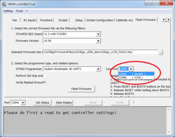
- Plugin the USB-to-serial adapter and click again on the drop down box of the serial connector for programming. Select the new one.
- The board has two buttons, the boot and reset button. When the board is started, the very first thing the firmware does is checking if the boot button is currently pressed. If it is, then the bootloader mode is entered, else the normal operation starts. The best way of entering the bootloader mode is hence to press the boot button and while it is pressed to press and release the reset button to initiate a hard reset.
- Check if the board is in bootloader mode. When the board appears to be dead (green and red LEDs off, the yellow LED is irrelevant), then it is brought into bootloader mode successfully, if the green and red LEDs are blinking, it is in normal operation and obviously the boot button was not pressed while the reset button was released.
- Now the board is listening on the RC pins for serial data, the USB-to-serial adapter is connected, and the correct COM port of the adapter is selected, so you can click on the [Flash Firmware] button.
- A black DOS box will open and either return an error that the UART connection is not responding or a sequence of downloading and verifying the firmware is shown.
If this is a first-time flash of a "virgin" board, then Windows will start with installing the USB driver directly after the flash has finished. This can take quite some time. Do NOT interrupt the install process.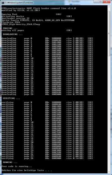
- After the reset, your board is fully operational and you may disconnect the USB-to-serial adapter.


The process is also nicely described in this video by rcgroups user alcurtis93:
Quick Trouble Shooting:
- It is strongly recommended to also read the How to flash firmware page for trouble shooting.
- The board has no power - connect the board to the computer via USB to power it.
- The pins labeled UART are used for flashing - which is wrong, the RC pins should be used.
- Wrong serial port is selected in the tool.
- The black DOS box doesn't show up, e.g. because the firmware .zip file was not extracted.
- The above steps run though and the black DOS box shows the first two [OK] messages, but the downloading and verifying message lines are not be present and a firmware is not flashed. Some few boards are shipped with enabled read&write protection of the flash, which causes the issue. Go to Removing Read&Write Protections.
- In case of troubles with the USB driver, consult the FAQ: Which drivers are needed for the USB?.
Related wiki articles:
Checking Connection to the GUI
Let's next check if the STorM32-BGC is indeed operational, and communicates with the GUI. Note that firmware and GUI versions must match.
- If connected, disconnect a USB cable and/or USB-to-serial adapter. Click on the COM port selector in the left bottom and memorize the list.
- Then plug in the STorM32 board via the USB cable to power it. When clicking on the drop down for the COM port selector, it should now show an additional one.
If the board has a firmware installed and this is the first-time connection via USB to your PC, then Windows will install the USB driver for the STorM32 board. This can take quite some time. Do NOT interrupt the install process.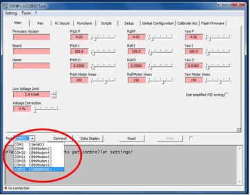
- Go to e.g. the [Main] tab and click on [Connect] or [Read] to validate the connection with the board.
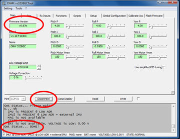


It's a good occasion now to also learn about the [Read], [Write] and [Write+Store] buttons and to read FAQ: How does Read, Write, and Store work?.
Quick Trouble Shooting:
- Wrong COM port selected.
- Firmware and GUI version numbers do not agree.
Related wiki articles:
- FAQ: Which drivers are needed for the USB?
- FAQ: How does Read, Write, and Store work?
- FAQ: How to enter precise parameter values?
Hardware Setup
The Camera IMU
The camera IMU needs to be mounted such that it measures all camera movements. Its actual position does not matter, behind the camera, on the pitch arm, below the camera,... anything will work. The only thing to watch out for is that its axes are aligned with the camera axes. Each axis has to be either horizontal or vertical. Just imagine that the sensor would measure that the horizon is level but because of a misalignment the camera does hang slightly to one side and hence the horizon in the video is not level.
A typical beginners mistake is to route the IMU cables in close proximity to the motor cables. This may however lead to I2C errors, and subsequent artifacts such as a "freezing" of the gimbal. If in doubt, please check the web, it is full of discussions on this topic, and/or consult the I2C Error Compendium. BTW, the STorM32 NT concept offers an ultimate solution to this issue by abandoning the I2C bus altogether (for more info see STorM32-NT BGC).
Mounting the STorM32 Board
One of the outstanding features of the STorM32 board is its 2nd IMU support. In fact the board has such an IMU on-board already. To make use of it, the board needs to be mounted such that it measures the movements of the copter frame. The direction does not matter as long as it measures the frame's movements. In case this is not possible, either the 2nd IMU support has to be disabled, or another external IMU can be mounted to the frame and connected to the frame I2C connector, labeled I2C#2. As for the camera IMU, also the axes of the 2nd IMU have to be vertical or horizontal, respectively.
Related wiki articles:
Electric Connection and Insulation
The IMUs go to their corresponding I2C plugs: The camera IMU goes to the picoblade connector labeled I2C next to the USB connector. On the backside of the board is the I2C#2 connector for the optional frame IMU. The camera IMU must go to the port I2C, near the USB plug! Your board may have been shipped with a IMU pre-connected to port I2C#2, which is incorrect.

One thing we found out the hard way is to never mount the board or the IMUs with metal screws and/or metal distance sleeves. Always use plastic ones. Not only does this help to avoid electrical problems but also the I2C bus can be sensitive to the nearby metal parts, leading to massive error rates on the I2C bus. Without a continuous readings of the IMU positions the entire purpose of the gimbal is forfeit.
Make also sure that the IMUs are mounted rigidly, so that they measure the actual position.
Related wiki articles:
Gimbal Mechanics
Before using a gimbal, it is absolutely necessary to balance it and to ensure minimum resistance to rotations (friction in bearings, stiff cables, etc). Any improper balance or resistance to rotation will make setting up the gimbal more difficult or even impossible. The goal shall be to rotate the camera in the gimbal and it should stay in that position by itself. In other words, the center of gravity should be in the center of all gimbal motor axes. Just imagine the camera's center of gravity is way below the pitch axis (looking with the camera up and down). It would act like a pendulum. So just because your copter does accelerate forward, the gimbal pitch motor has to hold against the mass inertia. You will need very strong motors and lots of energy which is a waste. On the other hand, if the gimbal is balanced properly, the motor only has to compensate the copter rotations, wind resistance and inertia when rotating the camera to point to somewhere else.
Related wiki articles:
Powering the Gimbal
For the motors the 5 V supply of the USB bus is too low. So, the motors will work only if a battery with sufficient voltage is connected. That is the reason why e.g. flashing the firmware is done using USB power only, as we do not want the motors to get power in that case. The battery connector can handle any voltage from 6 V to 18 V. Connecting the PC via the USB cable while the board is powered via a battery is no problem at all. The order does not matter, first USB then battery, or vice versa, both will work.
Motor Connectors
The board has three connectors for the motors labeled Mot0, Mot1 and Mot2. Before connecting any motor, it is a good idea to measure the resistance of the motor windings and the motor frame. The three motor cables should have an electrical resistance of 12 Ohm or more and be completely isolated from the motor housing. If the resistance is too low, the amount of amps flowing through the motor might be too high for the board driver. If one of the motor cables has a short to the motor housing, the entire gimbal and maybe even the frame gets the motor voltage.
The usage of the three connectors is
- Mot0: Pitch motor to point the camera up/down
- Mot1: Roll motor to stabilize the horizon
- Mot2: Yaw motor to turn the camera left/right
The motors need to be connected in this order to the motor ports. The three wires of a motor in contrast can be connected to its port in any order, here the order does not matter.
Summary
Now the motors are connected, the IMU(s) are connected, the battery power cable is ready, and its polarity double-checked.

Basic Controller Configuration
Now it's time to set the most important parameters, namely the IMU orientations and motor parameter values, which are located on the [Gimbal Configuration] tab. Without that, the controller can't do even the most basic operations. Setting these parameters correctly by hand is difficult, however, the GUI provides the [Configure Gimbal Tool], which makes that very simple.
You should be prepared to know the number of poles of your motors, as well as be ready to connect a battery on demand (if you haven't already plugged in a battery).
In the following the gimbal MUST be at rest and NOT be moved at all times (unless you're specifically asked to do differently). Ergo, don't hold the gimbal in your hands. Also, a camera MUST be installed in the gimbal. Without camera gimbals don't work properly.
- Change to the [Gimbal Configuration] tab. There you find the parameter fields for the IMU orientations, motor poles, motor directions and motor startup positions. To set them, run the [Configure Gimbal Tool].
- In the welcome screen you can select what to configure. The individual steps are grouped into Steps I and Steps II, and some finishing steps. You want to do all, and hence just click on [Continue].
- You are now asked to position the gimbal and camera. The gimbal should be in its standard default position. Adjust the camera manually such that it is level and points into the forward direction of your copter. You might not be able to do that perfectly because of the motor magnets, but you should get that better than to within 15°. Once the camera is in forward position click on [Continue].
- Now you are asked to pitch the entire frame inclusive camera downwards by 45°, as if you would want to film the ground in front of the copter. So you lift the frame such that both, frame and camera, point downwards. Importantly, the camera should not move and keep its position relative to the frame. If it does move then you should consider balancing the camera better. Also, avoid roll movements. Anyway, the goal in this step is to measure the effect of a downturn by 45° degree on the IMU's signals. The IMUs do measure the acceleration values, and as we are static its the earth gravity. For example, the reading in normal position might be x/y/z = 0 g/1 g/0 g. When pitching downwards, the values may change to 0.7 g/0.7 g/0 g, and from that we know the IMU's orientations.
- Once the IMU orientations were determined, their values are shown and you can (should) put the gimbal back to normal position. When you can continue with the next step.
- The next important step is to set the motor pole counts for each motor. This is information you should get from the motor vendor. Data like N12P14 means 14 poles.
- On the next screen you are informed that all motor direction values will be set to "auto". Click [Continue].
- This completes the settings of Steps I, and you can proceed with adjusting the parameters of Steps II.
- For the next steps to work, the gimbal has to be started up with enabled motors, and a battery must be connected. The GUI will check for that, and will ask you to connect a battery if required. Do as advised.
- The gimbal will now go through it's initialization steps, which you can follow in the screen. Please wait until it reaches the NORMAL state. You should see the green LED go solid, as well as hear a beep. You are reminded to keep the gimbal in normal position and at rest during all this.
If this step doesn't complete or an error occurs see the Quick Trouble Shooting section below, and please take any recommendations from there seriously.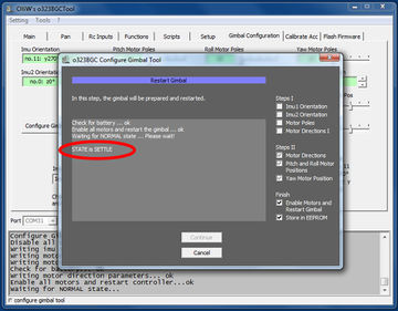
- On the next screen you are informed that the motor direction values will be determined for all motors. Click [Continue].
- In a further screen you are informed that the motor startup positions for the pitch and roll motors are determined. Click [Continue].
- Now you are asked for another important step, namely to align the camera such as to point forward. Use the buttons to turn the camera until you're satisfied. The goal of this step is to align the camera with the 2nd IMU. A precise alignment is required for the 2nd IMU function to work correctly. You don't have to overdo however, a visual accuracy of the alignment is sufficient.
- This completes the settings of Steps II. What is left is to store all values in non-volatile memory, and to restart the gimbal.
- The results of the above steps can be seen in the [Gimbal Configuration] tab, which got updated with the new IMU orientations and motor parameters. Also the motors are enabled, and the system is functional now.


Quick Trouble Shooting:
It may happen that the tool gets stuck in step 10. This generally indicates a serious problem with the setup, and not the controller. Examples are:
- Motors are not connected to the correct ports.
- Motors are not working properly because of e.g. a broken wire or bad connection.
- The IMU(s) do not work properly because they are connected to the wrong ports, or step 4 wasn't done correctly.
- I2C errors occur because of inappropriate routing of motor and I2C cables (consult also the I2C Error Compendium).
- PID parameters are totally wrong for the gimbal.
- Read also the Quick Trouble Shooting section in the next chapter!
Related wiki article:
First Startup
After the above steps were completed, the STorM32 controller was reset and hence will start up now.
At startup, the controller goes through its initialization steps, which typically takes about 20 - 25 seconds. Note that the gimbal should not be moved until the initialization is finished and the controller has reached normal operation. This is indicated by greed LED going solid, and - if enabled - by a beep.
Initialization Steps: strtMOTOR - SETTLE - CALIBRATE - LEVEL - AUTODIR - RELEVEL - NORMAL
- strtMOTOR: The motors are turned on, and moved into the position specified by the startup motor position parameters.
- SETTLE: In order to calibrate, the gimbal has to be stable, it should not be moved. For a copter that is quite simple as the copter is on the ground. A handheld device needs to be put at a table to remain in position for a few seconds.
- CALIBRATE: Calibrates the sensors. Takes a second or so.
- LEVEL: This is the point where the motors will moved such to level the camera in pitch and roll axis. The yaw motor is under power, so you can feel some resistance, but it is not moved.
- AUTODIR: Here the motors are moved slightly around and from the sensor changes the controller determines the motor directions.
- RELEVEL: Since autodir moved the camera, it is quickly brought back in a horizontal position.
- NORMAL: This is the final stage; the PID controller is activated and the gimbal is operational. Simply move the camera out of position by hand, move the frame,... whatever you do the camera should remain stable. With a 2nd IMU enabled you can pitch the camera indefinitely, you can yaw the camera indefinitely or roll the camera by maximal +-80° or so. Larger roll angles are not possible as when the pitch and yaw axes become aligned, and pitch and yaw movements cannot be distinguished anymore (gimbal lock). Without 2nd IMU, the yaw and roll ranges are as before, but the pitch range is limited to +-45°.
Led Signals: The progress of the initialization is also indicated by the green LED on the board: During initialization it flashes with varying frequency. When initialization has finished and NORMAL state been reached, it goes solid. If beeps are activated, then the motors will emit a sound at the end of initialization, which can be very convenient. The current state of the controller can also be seen in status line the GUI, or the Data Display.
Quick Trouble Shooting:
- The gimbal controller levels the camera, but only very, very slowly: The gimbal had been moved before the initialization has finished. Wait until the NORMAL state has been reach (green LED = solid) before moving the gimbal.
- The gimbal moves constantly around, never finding the level position: The pitch and roll motors are not connected to Mot0 (Pitch) and Mot1 (Roll) but reverse. Hence the control logic does measure that pitch has to be changed by -5°, applies the proper movement sequence to the motor but all that happens is that suddenly the roll value is off by -5°. Make sure the motors are connected correctly.
- Camera turns upside down or things like that: The IMU orientation is wrong.
- Gimbal starts shaking, makes high frequency noises and things like that: This would be normal as we have not yet tuned the PID values for the motor control loop. In case that happens, set for all motors the P, I and D values to very low numbers but not zero (P=0.10; I=5.0; D=0.0050) and write them to the board. This will cause the gimbal to be slow when correcting movements but at least you can prove all is functional.
- The motors receive power only briefly after startup but are when shut off and the red and green led start blinking fast, and the controller remains in LEVEL state: The controller could not level the camera within a certain time and hence shut off the motors for safety. This can happen for various reasons, such as that there is a mechanical constraint to the camera, one or more motors do not operate properly because of e.g. a broken motor wire or bad connections, or that the gimbal has not been assembled fully.
Next Step - PID Tuning
At this point the gimbal may already stabilize the camera. However, usually, the camera is not yet stabilized perfectly, since the PID parameters in the [Main] tab are not yet optimal. The gimbal may even start to show weird shaking or make high frequency noises, which indicates that the PID values are totally off. So, in any case the next step should be to tune the gimbal.
See the PID parameter Tuning Recipe for adjusting those.
You are also strongly encouraged to check out the Video Tutorials; there is a collection of some quite good videos available.
Comment: For good camera stability you need to spend at least a minimum time with PID tuning. The default PID values are chosen such that they work with most gimbals in the sense that the gimbal doesn't freak out. They therefore are necessarily "bad" in terms of good PID control or camera stabilization, respectively.