Boards
Jump to navigation
Jump to search
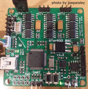
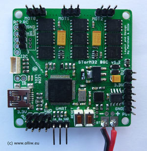
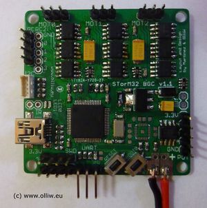
At present, three different versions of STorM32-BGC boards are in use (v0.17/v1.0 boards are deprecated).
Comments:
- The boards can be populated with different motor drivers: the TC4452 driver in DFN package or the TC4452 driver in SOIC package; the DFN package allows somewhat higher motor currents.
- The boards can in principle be populated with different microcontrollers; the standard configuration is a STM32F103RC.
- For a detailed description of the various connectors on the board see Pins and Connectors.
- To avoid confusion/misunderstandings please note: The boards provide many features hardware-wise, but not all are yet supported by the firmware.
STorM32-BGC v1.3
|
|
STorM32-BGC v1.2
Differences to the v1.3 board:
- voltage regulator: smaller SOT223 package
- only 2 auxiliary ports
STorM32-BGC v1.1
Differences to the v1.2 board:
- no Futaba S-bus support
- Spektrum satellite is supported, but no extra Spektrum connector on board
- no extra USB voltage protection diode
- voltage regulator: smaller SOT223 package
- only 2 auxiliary ports
Comment: The order of pins on the I2C#2 port is reversed to that on the I2C#1 port; please consider this then connecting an MPU module to the I2C#2 port. Note that this does not apply to the witespy board; here the issue has been resolved by a smart plug.


