The technical specifications of various STorM32 boards are presented, as far as they are known. To find suppliers/vendors please go to Where to buy STorM32 boards. For a detailed description of the various connectors on the (original) boards see Pins and Connectors.
"Original" STorM32 Boards
At present, the versions v1.1, v1.2, v1.3, and v3.3 are in use (v0.17/v1.0 and v2.4 boards are deprecated). The commonality of the v1.1, v1.2, and v1.3 boards is a resistive voltage regulator and the TC4452 motor drivers. The v3.3 board is specifically designed for NT and T-STorM32, and is distinguished by a low-noise 5 V switching voltage regulator, EPS8266 and CAN bus support. It has no motor drivers on board.
STorM32-BGC v3.3

STorM32 board v3.3 specifically designed for NT and T-STorM32
- MCU: STM32F103RC at 72 MHz
- motor drivers: none
- voltage regulator: 5 V, 0.6 A low-noise switching regulator
- on-board MPU9250 or ICM20602 IMU, connected to SPI
- 2 NT ports and one NT-X port
- ESP port for ESP8266 modules
- CAN bus port
- on-board CP2102, enables flashing per USB
- Futaba S-Bus
- Spektrum satellite
- up to four PWM/Sum-PPM inputs/outputs
- joystick port for two axes
- 2 auxiliary ports, one BUT port
|
- supply voltage: 6 - 27 V or 2 - 6S
- motor current: depends on used NT motor modules
- board dimensions: 40 mm x 25 mm, 35 mm bolt to bolt, holes Ø3 mm
|
Comment: This board has no motor drivers; NT motor modules need thus be used.
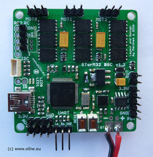
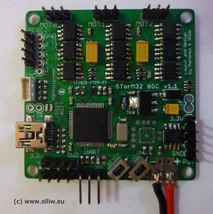
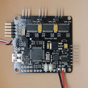
STorM32-BGC v1.3

STorM32-BGC board v1.3 with motor drivers in SOIC package
STorM32-BGC board v1.2 with motor drivers in DFN package
STorM32-BGC board v1.1 with motor drivers in SOIC package
- MCU: STM32F103RC at 72 MHz
- motor drivers: TC4452
- voltage regulator: linear resistive
- on-board Bluetooth (optional)
- on-board 6DOF IMU (MPU6050)
- IR led
- Futaba S-Bus
- Spektrum satellite
- up to seven PWM/Sum-PPM inputs/outputs
- joystick ports for all three axes
- additional I2C port (I2C#2)
- 3 auxiliary ports
- BUT port
|
- supply voltage: 6 - 18 V or 2 - 4S
- motor current: max. 1.5 A per motor
Comment: This is not yet fully exploited and also depends on the package, with DFN packages motors with resistances of 12 Ohm or larger have been tested to be well handled at 4S, motors with 10 Ohm may be handled with care; for the latest summary see here (for details see also here, here), here and here).
- board dimensions: 50 mm x 50 mm, 45 mm bolt to bolt, holes Ø3 mm
|
STorM32-BGC v1.2
Differences to the v1.3 board:
- voltage regulator: smaller SOT223 package
- only 2 auxiliary ports
STorM32-BGC v1.1
Differences to the v1.3 board:
- no Futaba S-bus support
- Spektrum satellite is supported, but no extra Spektrum connector on board
- no extra USB voltage protection diode
- voltage regulator: smaller SOT223 package
- only 2 auxiliary ports
WARNING: The pins of connector I2C#2 are in reverse order to those of connector I2C, which implies also reversed voltage polarity. Pay attention to that before connecting a second IMU to the I2C#2 port.
Descendants
The STorM32 boards listed here are based on/derived from the layout of the "original" board designed by Martinez and OlliW, but modified in some ways.
GLB STorM32 v1.31

STorM32-BGC board v1.31 with DRV8313 motor drivers
- MCU: STM32F103RC at 72 MHz
- motor drivers: DRV8313
- voltage regulator: switched step-down
- on-board Bluetooth (optional)
- on-board 6DOF IMU (MPU6050)
- IR led
- Futaba S-Bus
- Spektrum satellite
- up to seven PWM/Sum-PPM inputs/outputs
- joystick ports for all three axes
- additional I2C port (I2C#2)
- 3 auxiliary ports
- BUT port
|
- supply voltage: 9 - 25 V or 3 - 6S (according to the specs given by GLB, not yet confirmed in practice)
- motor current: 1.5 A
Comment: The board uses the same motor drivers as the BaseCam SimpleBGC 32-bit board, and the same spec can hence be expected, but the real capability has not yet been tested in practice.
- board dimensions: 50 mm x 50 mm, 45 mm bolt to bolt, holes Ø3 mm
|
Comment: The 3.3V power on this board seems to be quite weak, and has caused repeatedly issues with powering NT modules. One single NT IMU seems to be ok, but not more. See also [[1]].
Comment: There had been cases with a problem with EMI noise on the 433/915 MHz band from this board, see [[2]]. For solutions see [[3]]. EMI noise seems not to be a problem in general, however, see [[4]].
STorM32 v1.32
STorM32-BGC board v1.32 with DRV8313 motor drivers
- MCU: STM32F103RC at 72 MHz
- motor drivers: DRV8313
- voltage regulator: linear
- on-board Bluetooth (optional)
- on-board 6DOF IMU (MPU6050)
- IR led
- Futaba S-Bus
- Spektrum satellite
- up to seven PWM/Sum-PPM inputs/outputs
- joystick ports for all three axes
- additional I2C port (I2C#2)
- 3 auxiliary ports
- BUT port
|
- supply voltage: 9 - 18 V or 3 - 4S
- motor current: 1.5 A
Comment: The board uses the same motor drivers as the BaseCam SimpleBGC 32-bit board, and the same spec can hence be expected, but the real capability has not yet been tested in practice.
- board dimensions: 50 mm x 50 mm, 45 mm bolt to bolt, holes Ø3 mm
|
Comment: For NT setups this board might be preferred over the v1.31 board, since it uses the same linear regulator as the v1.3 and not the weak switching regulator of the v1.31. For older I2C-based setups it's probably better to get a v1.31, which tends to be cheaper and especially offers a switching voltage regulator.
Witespy STorM32-BGC v1.1 Mosfet Version

Witespy STorM32-BGC v1.1 board with mosfet motor drivers
- MCU: STM32F103RC at 72 MHz
- motor drivers: mosfet
- voltage regulator: linear
|
- supply voltage: ? (no specs given by witespy)
- motor current: ? (no specs given by wiitespy)
- board dimensions: 50 mm x 50 mm, 45 mm bolt to bolt, holes Ø3 mm
|
Third-Party Boards
The terms of usage of the STorM32 project allows, and in fact encourages, making own hardware, for both DIY and commercial purposes, without restrictions.
Micro STorM32 BGC
- MCU: STM32F103RC at 72 MHz
- motor drivers: TC4452
- voltage regulator: linear (LG33)
|
- supply voltage: 7.4 - 16.8 V or 2 - 4S
- motor current: 1.5 A (according to the given specs, whatever this means)
- board dimensions: 40 mm x 22 mm, no mounting holes
- no BOOT0 and RESET buttons
|
Comment: This board is suitable only for 2S (see [[5]]), with higher voltages it gets quite hot and may malfunction. Read also this: [[6]]. The board can only be flashed with a ST-Link adapter via SWD, it cannot be flashed via the "usual" procedure. Many pins/ports are not available. Overall, this board cannot be recommended, except for special applications.
GLB Mini STorM32 BGC

GLB Mini STorM32-BGC board with L6230 motor drivers
- MCU: STM32F103RC at 72 MHz
- motor drivers: L6230
- voltage regulator: switched step-down
|
- supply voltage: 7 - 25 V or 3 - 6S (according to the specs given by GLB, whatever this means)
- motor current: 1.5 A (according to the specs given by GLB, whatever this means)
- board dimensions: 42 mm x 30 mm, ? mm bolt to bolt, holes Ø? mm
|
AliExpress Mini STorM32 BGC

AliExpress Mini STorM32-BGC board
- MCU: STM32F103RC at 72 MHz
- motor drivers: DRV8313
- voltage regulator: linear
|
- supply voltage: 7.4 - 16.8 V or 2 - 4S (according to the specs given by AE, whatever this means)
- motor current: 1.5 A
- board dimensions: 40 mm x 30 mm, 43 mm pitch ??, holes Ø2 mm
|
Comment: The info given on some pages is definitely wrong in some aspects. What we know so far (see also here and followup posts):
- DRV8313 motor drivers do not allow 2S operation
- only the RC port is available
- SBus is not supported
- BT module cannot be installed on-board


