The old MAVLink gimbal protocol, which is based on the DO_MOUNT_CONFIGURE and DO_MOUNT_CONTROL commands, has plenty of issues (see here) and really needs replacement. I had the privilege and pleasure to contribute some key ideas to the MAVLink Gimbal Protocol v2, but currently this protocol is quite specific to PX4’s needs and does not (yet) provide solutions to the practical cases as we encounter them. So, given that MAVLink allows for dialects, I went on and designed a STorM32 dialect (storm32.xml).
The new STorM32 MAVLink gimbal protocol not only overcomes the issues with the old gimbal protocol, but also introduces a clean concept for the communication and message flow, which is based on three logical layers, somewhat similar to how modern software is architectured. From top to bottom, the three layers are „super modes“, „gimbal manager“ and „gimbal device“. Well, „super mode“ admittedly sounds somewhat silly, and in the STorM32 dialect it is thus called „qshot“, but „super mode“ actually catches it quite accurately, so I use that term here.
1. Concept
2. Physical Devices and Communication Links, Typical Topologies
3. Status Fields and Flags
4. Initialization Protocol
5. Attitude Quirks
1. Concept
The central part of the concept is the gimbal manager. On the one hand, all communication related to the control of the gimbal is going through – and has to go through (!) – the gimbal manager. This enables the gimbal manager to oversee the communication with the gimbal, and prevent and resolve conflicts in cases where several clients want to control the gimbal. This is actually the gimbal manager’s main job and responsibility, to manage several clients and to deconflict in case of conflicting requests. On the other hand, it provides also a higher-level abstraction.
In some way, the gimbal manager can be seen as a semaphore. Depending on implementation it can be binary or counting, but usually it will be neither but follow more complicated rules (vide infra). It is a semaphore in the sense that it manages the access to the resource ‚gimbal‘.
On the protocol level this is achieved by a clear separation of the messages into those which describe the communication between gimbal manager and gimbal and those which describe the communication between gimbal manager and clients. The control message from the gimbal manager to the gimbal is named GIMBAL_DEVICE_CONTROL, and the control messages between the gimbal manager and the clients are named GIMBAL_MANAGER_CONTROL_XXX (the ‚XXX‘ indicates that there are several control messages available).
Comment: The names of the messages of the STorM32 gimbal protocol are all prepended with a STORM32_, which is however usually omitted in this article for brevity.
For notation, the gimbal is called gimbal device in the concept. The reason is that a physical gimbal can be both gimbal manager and gimbal device at the same time; gimbal manager and gimbal device are logical entities, and not physical devices (they are actually pieces of code running on some device, and they can run on the same device but also on different devices). This should become clearer below in the next chapter.
Thus, the basic principle is as simple as this:
- Only the gimbal manager is allowed to control the gimbal device by sending GIMBAL_DEVICE_CONTROL messages, while all clients must use GIMBAL_MANAGER_CONTROL_XXX messages.
Each gimbal device is associated to one gimbal manager, and – in order to not have to rely on the goodwill of the clients but to enforce the rules – we also require:
- A gimbal device must only listen to the GIMBAL_DEVICE_CONTROL messages from its gimbal manager, but not to those from other gimbal managers, and it especially must not listen to any of the GIMBAL_MANAGER_CONTROL_XXX messages.
Makes sense, right :).
In addition, the gimbal manager supports higher level messages. Indeed, while the GIMBAL_DEVICE_CONTROL message carries grass-root data such as the attitude quaternion and provides a robotic-like interface, the GIMBAL_MANAGER_CONTROL_XXX messages are generally more „user-friendly“. We thus find:
- The gimbal manager provides a higher-level API or abstraction to the clients.
From the perspective of the integrator, this is probably the most welcome aspect of the concept.
A further important aspect of the gimbal manager concept is that it makes it easy to modify the behavior. For instance, if it should happen that the integrator is not happy with the behavior of a gimbal manager as it is provided by a specific implementation or flight stack, then she just needs to disable it and link in her own gimbal manager implementation. This provides great flexibility without having to change the code of the clients and gimbal device.
Remains to clarify what the super modes are. Many tasks which involve the gimbal do in fact not only involve the gimbal but also other components in the MAVLink network, such as the autopilot, camera, or companion computer. It is generally difficult to assign such tasks to one component, and their realization is also highly implementation specific, which makes standardization difficult. These tasks are however usually of most value to the user, so some mechanism needs to be provided.
Consider for instance a gimbal which should follow a target. Clearly, in order to achieve this, „someone“ needs to know the vehicle position and the target position, and translate them into the proper gimbal movement. The vehicle position comes from the autopilot. The target position could be send by the target to the GCS which it when forwards to the vehicle, or it could come from the camera using some AI target detection, and so on. So, is this now an autopilot task, a camera task, a gimbal task, or a companion task? Not easy to decide. The approach of the STorM32 dialect is to not provide a specific answer, to consider it implementation specific, and to therefore only provide the primitives to inform all involved parties about which task shall be executed. If one thinks about it, this is exactly what the mode field in the old DO_MOUNT_XXX command was doing, which allowed us to set e.g. RC_TARGETING or GPS_POINT. However, since it was placed in the MOUNT commands the result was that also the autopilot had to digest and react to a MOUNT message in order to e.g. yaw the copter accordingly, and MOUNT messages were wildly send around. The STorM32 dialect resolves such logical, conceptual weirdness by considering these sort of tasks as what they are, namely modes which are not attached to a single component but involve many components. This is what „super mode“ is supposed to mean.
To a large extend the super modes are actually what a user would selects in a GCS. For instance, the user would select gimbal targeting, or RC targeting, or one of various quick shots, or even simply retract. This all would be super modes.
The concept could be summed up in a pictorial representation as follows:
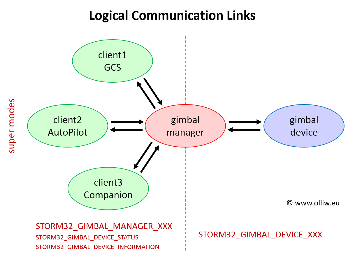
The clients communicate with the gimbal only via the gimbal manager messages and commands, but may receive status and information messages from the gimbal device. The gimbal device is controlled however only by its gimbal manager. The clients may listen to, react to, or set the super mode, as desired by the implementor. The gimbal manager or gimbal device would however not listen to or react to the super mode.
A primary challenge for any concept is to manage the various possible states in which the gimbal device, the gimbal manager, and the clients can be. On the protocol level this is achieved by a set of flags and fields, and a set of messages which are regularly reporting them. On the code level it is the job of the gimbal manager to sort things out. The flags & fields can be broadly distinguished into capability flags and status flags & fields. The capability flags describe the static properties and features of the gimbal device and the gimbal manager, which cannot change during run-time. The status flags & fields collect all those data which are dynamic, i.e., can change during run-time (here, dynamic does not mean that the data do actually change, only that they could change; similarly, static does not mean that they do not change, it means that they cannot change). The handling is such:
- The clients can request changes in the flags and fields, the gimbal manager evaluates them and makes a decision, and (regularly) broadcasts the result. That way the clients can determine if their request was accepted or not.
It is with the flags & fields where the new gimbal protocol becomes a bit more complicated than the old. But before I go into this, I first want to discuss in the next chapter the relation to the physical devices and communication links.
2. Physical Devices and Communication Links, Typical Topologies
As mentioned before, the gimbal manager and gimbal device are logical entities and not physical devices. This provides great flexibility, and for each setup the implementor or integrator can choose the option which she considers to be best.
Two Clients, one Gimbal
The simplest case consists of three MAVLink components, a GCS, an autopilot, and a gimbal of course (two clients and one gimbal). In terms of the above concept, this gives rise to two configurations: The gimbal device is clearly the gimbal, however the gimbal manager can be located on the autopilot or on the gimbal (technically, the gimbal manager could also be located on the GCS, but let’s not consider this, it’s not a realistic option). What this means is that the piece of code which is doing the gimbal manager function is either part of the autopilot code or part of the gimbal code:
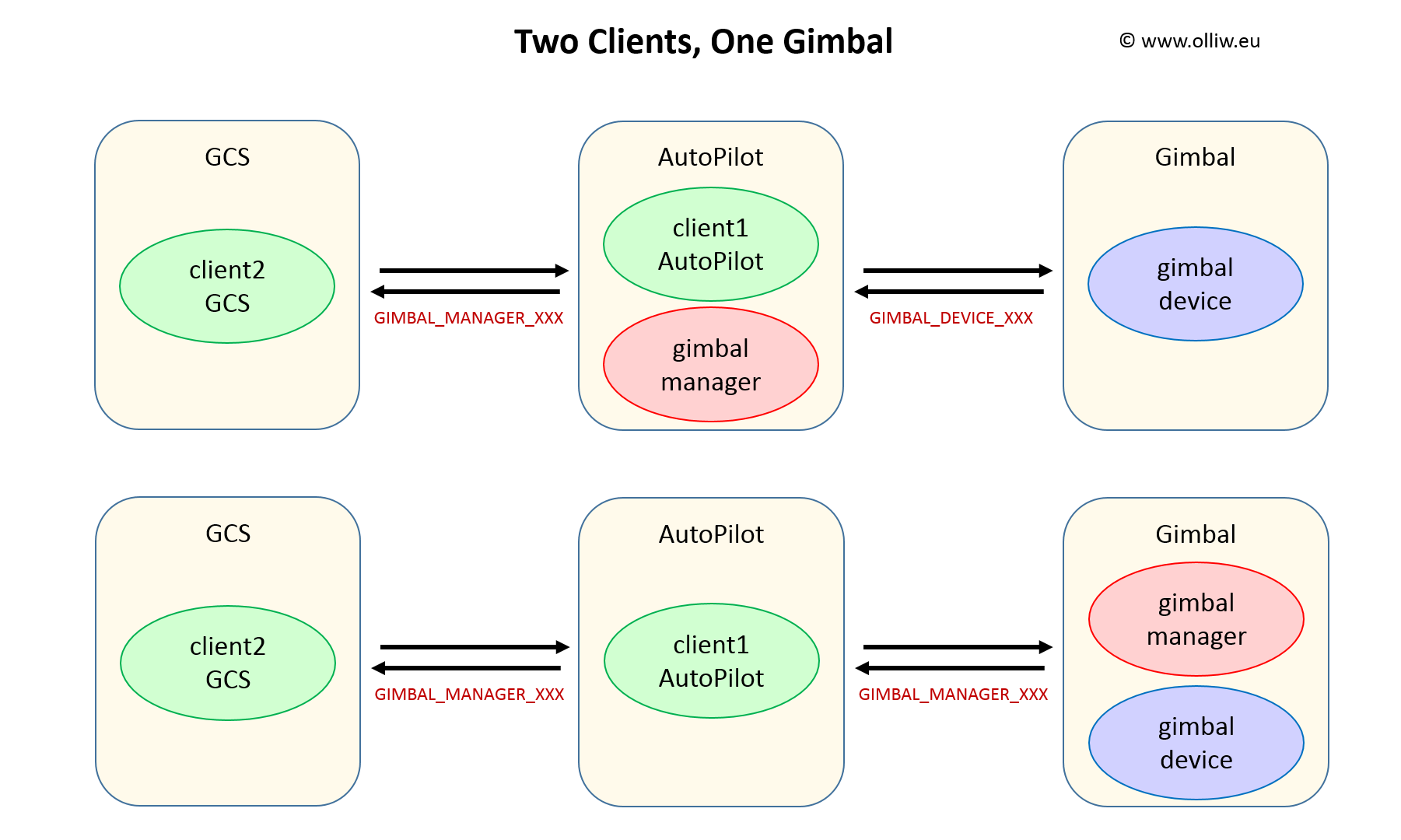
From the perspective of the clients both arrangements are equally fine, since either way they would communicate with the gimbal manager.
When the gimbal manager is located on the gimbal, GIMBAL_DEVICE_CONTROL messages are never physically send, and the gimbal exposes the GIMBAL_MANAGER_XXX API to the clients. The gimbal is then also responsible for deconflicting conflicting requests coming from the GCS or autopilot, i.e., it has to do exactly what the gimbal manager has to do.
It is added in passing that a gimbal device is not always existing. This occurs with „dumb“ gimbals, i.e., gimbals which do not support the new MAVLink protocol. This could be a gimbal which only speaks the old MAVLink gimbal protocol or a gimbal which is controlled by other means such as PWM signals. Then the gimbal manager would also do the traditional communication with the gimbal in order to mimic a protocol-v2 gimbal to the clients. A dumb gimbal could also be handled by creating a fake gimbal device, if that better suits one’s needs. The take-home message is that also „dumb“ gimbals can well be handled in the concept.
Three Clients, one Gimbal
Let’s now consider a system comprising a GCS, an autopilot, a companion computer, and a gimbal.
The four components can be connected to a MAVLink network in different ways with different topologies. Three typical examples are shown below. In addition, for each topology, the gimbal manager can be located on the autopilot, the companion computer, or the gimbal. This thus gives a rich set of configurations, which are all possible within the concept without any special precautions (except of course that the gimbal manager must be implemented on the device it is located on).
Of course, the MAVLink components which are at the interconnection of two or more links need to have routing capabilities, i.e., forward incoming MAVLink messages to the other links according to the MAVLink routing rules.
Locating the gimbal manager on the companion computer can often be of advantage. It could e.g. be realized with a Python script, which would be most easily modified or extended as needed.
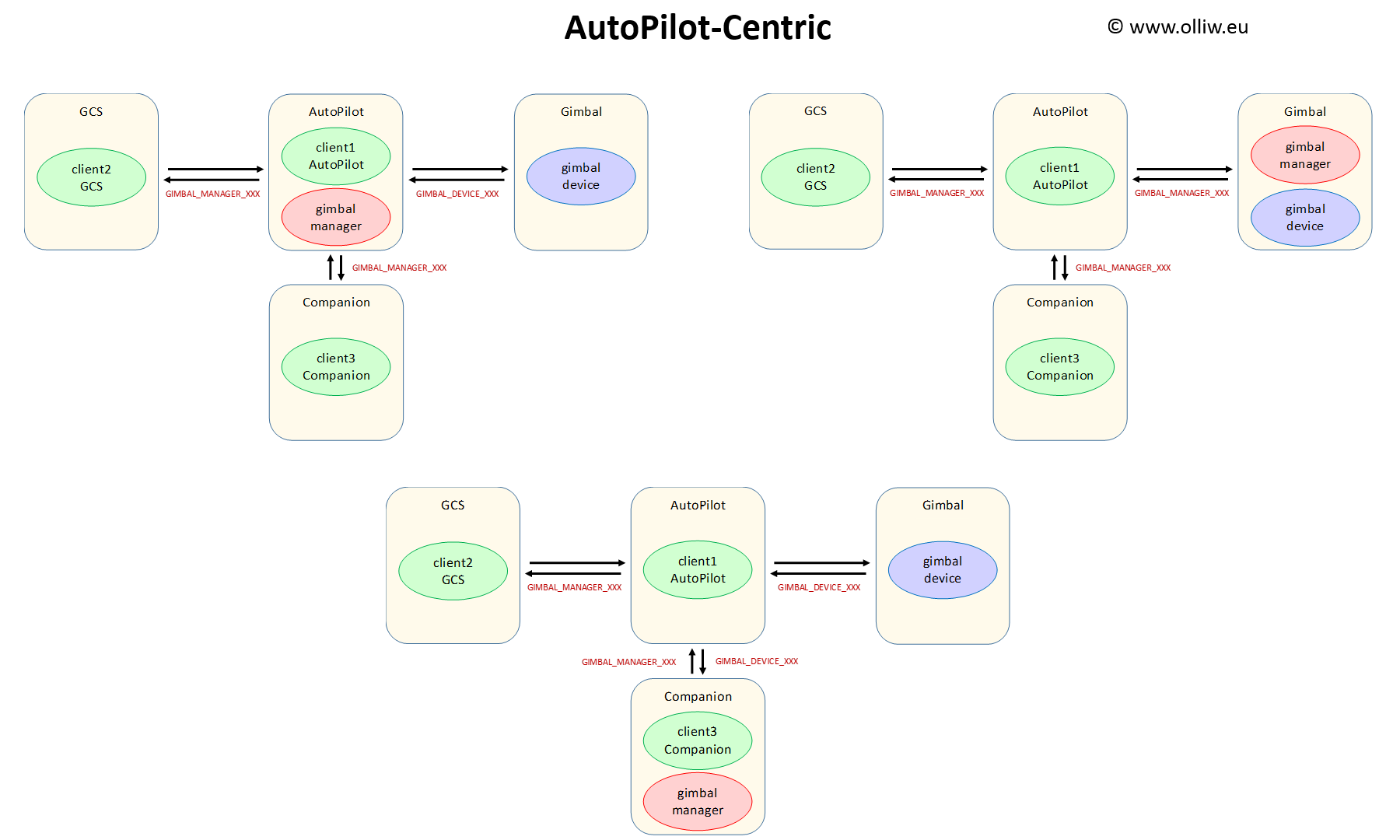
Autopilot-Centric
In this topology, the GCS, companion computer and gimbal are connected to the autopilot, yielding a star-like network with the autopilot at the center. This is probably the most widely considered arrangement with a companion computer in the system. It has the advantage that a router only needs to be implemented on the autopilot, which is the case anyways, so that it is relatively simple to get it going. The disadvantage might be that it uses relatively many links (UART ports) on the autopilot, which it may not have.
As discussed, the gimbal manager can be located on the autopilot, companion computer, or gimbal, which gives rise to these scenarios:
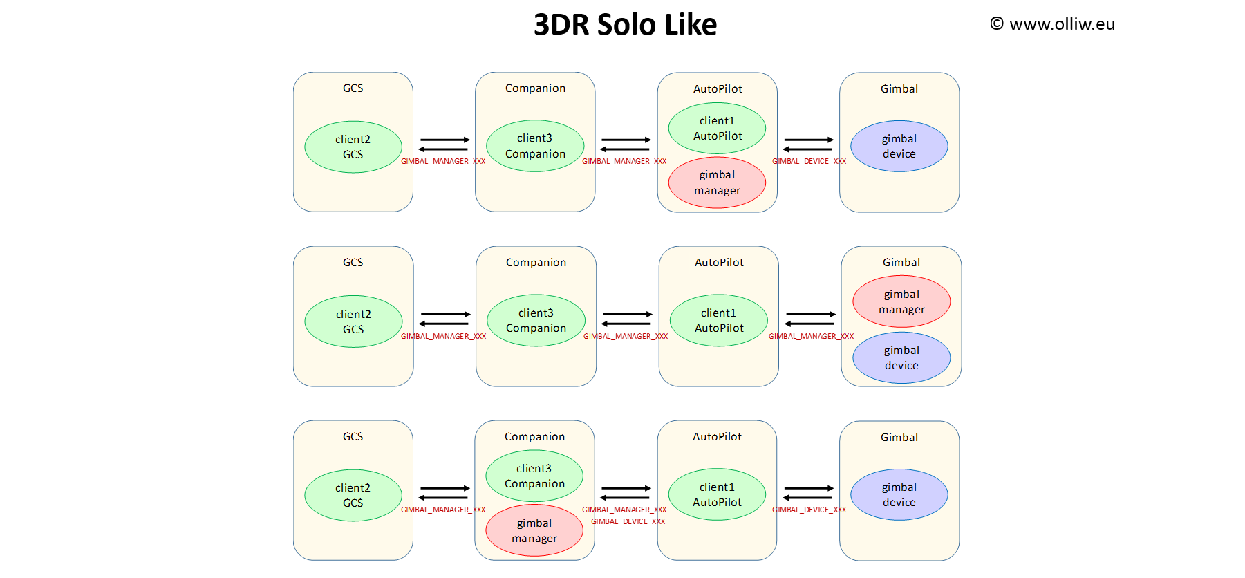
3DR Solo-Like
Here the four MAVLink components are connected to a chain, with the companion computer in between the GCS and the autopilot. This topology is akin to that used in the 3DR Solo, and that’s why I called it „3DR Solo like“, but the 3DR Solo certainly did not invent this topology. This topology suggests itself in applications where the wireless link between GCS and vehicle is using things like Wifibroadcast, DroneBridge, OpenHD, or other things of this sort where the link also functions as a companion computer. The disadvantage, at least for DIY hobbyists like me, is that the companion computer (and thus potentially also the RC control) sits in between ground control and autopilot, which means that any code mistake on the companion can result in a loss of control of the vehicle. It is thus not my preferred arrangement for developing (= fooling around :)).
Again, the gimbal manager can be located on the autopilot, companion computer, or gimbal, giving rise to these scenarios:
Companion-Centric
This is the last example I’d like to show. Here, the companion computer is positioned in between autopilot and gimbal. For brevity, I have not plotted all the cases, with the gimbal manager on the autopilot or the gimbal, and so on. You certainly got the pattern now.
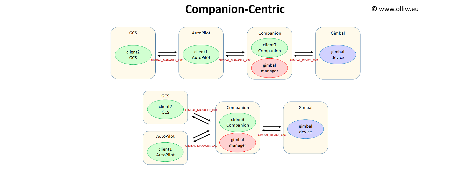
The first pattern is my preferred arrangement for my own experiments.
3. Status Fields and Flags
As mentioned in the above, the management of the states of the gimbal device, gimbal manager, and clients is a challenge and on the protocol level is achieved by a set of flags and fields. The design of the fields & flags is in fact not so easy, and it is here where the STorM32 dialect and the standard gimbal protocol v2 differ the most.
Three further concepts are introduced:
- Activity: Each of the clients can be in one of two states: It can be active or inactive. The gimbal manager adds up the control attitudes which it receives from all active clients and sends the resulting control attitude to the gimbal device. Inactive clients are ignored in the summation, and thus cannot control the gimbal. Note that active or inactive is not related in any way to whether a client is sending or not sending control messages; it is related to whether the control attitude which is received from a client is considered in the summation, or not.
- Supervisor: One of the clients can be the supervisor. Only the supervisor can set the activities of the clients. The gimbal manager ensures that only at most one client is supervisor, and also defines the rules for a client to become supervisor. These rules can be democratic, cooperative, priority based, or whatever is desired by the implemetor or is provided by the gimbal manager implementation.
- Profiles: The set of rules which determines how and when the clients become supervisor is called a profile. A gimbal manager implementation may provide several profiles among which to choose.
Technically, more than two clients can be active, but in practical situations it will be one or two (or none). Normally, only one client will be active, i.e., the gimbal will be controlled by only one client. This could be e.g. a GCS, or the autopilot executing a mission, or the companion running a quick shot. The typical case of two active clients would be that of nudging, e.g., when a companion runs a quick shot and the operator is allowed to nudge via the transmitter.
An important aspect of the concept is that only the supervisor can set the activities, but of all clients. This implies that a client cannot set itself to active (or inactive), unless it is the supervisor. This also implies that the supervising client does not have to be active itself. For instance, a GCS can be supervisor and be inactive but set a second GCS/transmitter to active, which would achieve dual-operator control. The supervisor has therefore full control over determining the activity of the clients, and in this sense is the dictator – but only for as long as it is the supervisor! It can lose its supervisor status as defined by the rules (aka profile) of the gimbal manager.
In many cases the GCS would be the supervisor, especially in „simple“ cases or implementations. For instance, when a mission shall be run by the autopilot, all it needs is that the GCS starts the mission and sets the autopilot to active, and similarly with quick shots. That is, simple use cases can be realized with simple solutions, requiring minimal implementation and communication. However, more elaborate and hence more powerful scenarios can also be realized. In the case of quick shots the companion computer could e.g. take over the supervisor status, which would give it full control over setting the activities, and release it at the end of the quick shot so that the GCS can retake it.
The rules by which a client can gain supervisor status are obviously a most crucial detail of a gimbal manager implementation.
The simplest case would be that of an „exclusive“ profile. Here, a client could gain supervisor status only if there is currently no supervisor. This is a maximally cooperative scheme: A client would become supervisor, but would have to release its supervisor status before another client could become supervisor. This is obviously a very simple scheme, and easy to comprehend. The disadvantage is that it requires quite some efforts in the implementation in order to coordinate the clients.
A more elaborate scheme would be a „priority“ profile. Here, a client could become the supervisor if there is currently no supervisor or if the client’s priority is higher than that of the current supervisor (the case of equal priorities needs further specification, it could e.g. be also exclusive). Such a profile needs more thought, but often makes implementations much easier, since less or no coordination needs to be implemented. This is a great advantage of priority-based profiles. It should be noted that priority-based profiles also allow a cooperative approach. That is, clients still can voluntarily release their supervisor status, which permits other clients to become supervisor. A typical priority sequence could be companion > autopilot > GCS.
The STorM32 dialect is prepared to support different profiles. This includes a customizable profile, for which the priorities can be explicitly set by the integrator.
4. Initialization Protocol
This picture sketches the initialization protocol I ended up with:
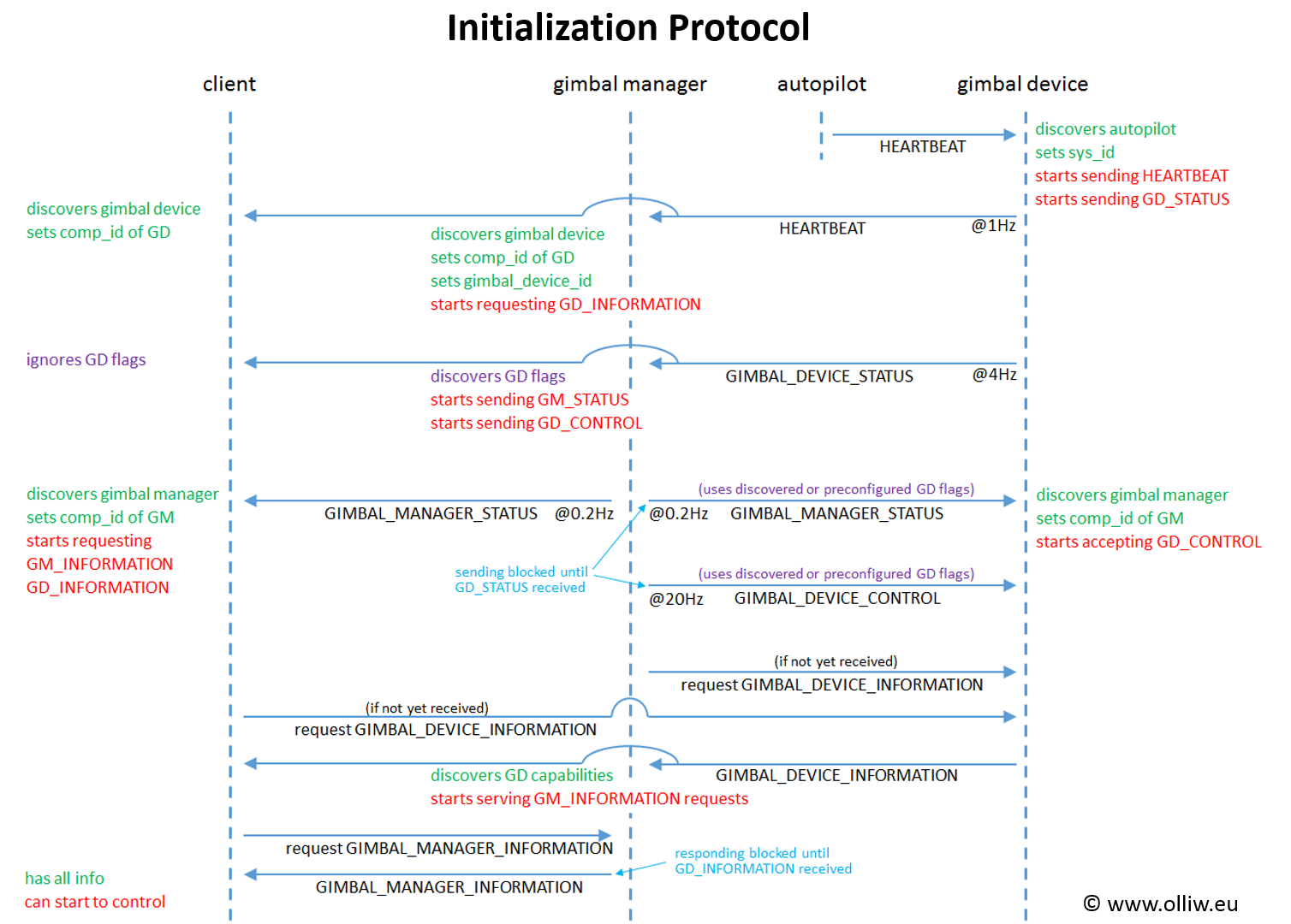
May look complicated, but it is less complicated than it looks like. The main task to achieve at initialization is a controlled flow of IDs, such as the gimbal ID, and of the capability and status fields & flags. After initialization all involved parties, gimbal device, gimbal manager and clients, should have synchronized flags. And this is what this protocol achieves. It also avoids the need for excessive configuration to get things going, i.e., uses auto-discovery wherever possible. This minimizes the need of parameters, and the need to configure them.
The sequence in words (each step is a prerequsite for the next step):
Gimbal Device
1. Waits for autopilot HEARTBEAT to auto determine system ID (can be skipped if system ID is pre configured).
2. Starts sending HEARTBEAT and STORM32_GIMBAL_DEVICE_STATUS.
3. Starts responding to GIMBAL_DEVICE_INFORMATION requests.
4. Waits for STORM32_GIMBAL_MANAGER_STATUS from its gimbal manager. Determines component ID of gimbal manager.
5. Starts accepting STORM32_GIMBAL_DEVICE_CONTROL messages.
Gimbal Manager
1. Waits for gimbal HEARTBEAT. Determines component ID of gimbal, and sets gimbal_id to it.
2. Waits for STORM32_GIMBAL_DEVICE_STATUS from its gimbal device. Determines gimbal device flags if wanted.
3. Starts sending STORM32_GIMBAL_MANAGER_STATUS.
4. Starts sending STORM32_GIMBAL_DEVICE_CONTROL.
5. Starts responding to STORM32_GIMBAL_MANAGER_INFORMATION requests.
6. Requests GIMBAL_DEVICE_INFORMATION and waits for response.
Client
1. Waits for gimbal HEARTBEAT. Determines component ID of gimbal.
2. Waits for STORM32_GIMBAL_MANAGER_STATUS from the associated gimbal manager. Determines component ID of gimbal manager. Ignores STORM32_GIMBAL_DEVICE_STATUS messages up to this point.
3. Requests GIMBAL_DEVICE_INFORMATION (if not already received) and STORM32_GIMBAL_MANAGER_INFORMATION and waits for responses.
4. Ready to go.
Depending on the situation, the initialization protocol can be different. The shown scheme is simple to implement and yet accommodates various situations.
5. Attitude Quirks
A not so trivial aspect of controlling a gimbal is related to its attitude. This topic is actually unrelated to any protocol, but is a fundamental point true for any gimbal, and it had been around since ever – it however may not have been so apparent so far and hence may not have become much attention.
Attitude can be represented in many ways, and probably the best known in the drone area are (aeronautic) Euler angles, DCM, and quaternion, and I assume that the respective advantages and disadvantages are also known to the reader. A strong feature of the new protocol is that it consistently uses quaternions for the communication with the gimbal device, i.e., in the STORM32_GIMBAL_DEVICE_XXX messages. However, in many cases one nevertheless wants to, or maybe even has to, convert to and from Euler angles. And this poses some issue since the aeronautic Euler angles, which are generally used for drones, do note bode well with gimbals.
Comment: I’d like to remind the reader that there are in total 12 different sets of angles allowed by Euler’s theorem, sometimes classified as Euler and Tait-Bryan or Cardan angles, proper or classic and improper angles, and so on. I choose the position to call them all Euler angles.
This is not difficult to see: The aeronautic Euler angles are characterized by having the gimbal lock at pitch = +-90°. However, tilting the camera down by 90° is really a very common and desired situation with gimbals! If one thus would use the aeronautic Euler angles for describing the gimbal orientation one would run in all sorts of mathematical issues. If one would, e.g., display them, then the roll and yaw angles would just go nuts when one approaches pitch = +-90°, even though the gimbal does behave perfectly fine! Not very user-friendly.
For the large majority of gimbals, Euler angles with the gimbal lock at roll = +-90° are the appropriate choice. And usually it is the Yaw-Roll-Pitch Euler angle set (the aeronautic Euler angles correspond to Yaw-Pitch-Roll in this notation). I will refer to them as „gimbal Euler angles“ in the following.
Unfortunately, the angles calculated with one Euler set are not consistent with those calculated with another Euler set. That is, one obtains numerically different values even for exactly the same camera orientation.
Control
Gladly, when roll is zero, both the aeronautic and the gimbal Euler angles coincide. That is, pitch and yaw angles calculated with either of them are then exactly identical. This is great, since for nearly all control purposes roll is in fact chosen to be zero and only pitch and yaw is controlled (in fact, the gimbal manager API largely exposes only pitch and yaw, for that reason). Thus, here the task is simple, as we now can use either Euler angle set for converting the desired pitch and yaw angles into a desired quaternion.
Unless we want to mix angles. Mixing corresponds to adding two attitudes. Three ways to do this are possible:
1. 
2. 
3. 
Choice 3 makes probably most sense, so it is what is used in the STorM32 gimbal, but in the code it may require recalculations of angles and quaternions.
Status
The situation is very different for the gimbal’s attitude reported in the STORM32_GIMBAL_DEVICE_STATUS message. Here, roll is not zero. It may be very small for most of the time, but it nearly never will be exactly zero, and the numerical issues mentioned earlier fully take place.
If the attitude needs to be converted to angles, e.g. for displaying, my recommendation is to not use the aeronautical Euler angles, but the gimbal Euler angles. This removes the instability, and in addition the pitch and yaw angles are consistent with the control angles, for the reason just discussed.
References
● MAVLink official documentation: MAVLink Gimbal Protocol v2
● Protocol design document: Proposal for new gimbal messages
● Collection of ideas: gimbals.txt
● Main issue in the MAVLink github repo: #1174