This page presents tutorials on Flashing of Silabs ESCs using owSilProg, and related topics such as the Windows program BLHeliTool, the programming box BLHeliBox, and the Bluetooth extension:
- Building an owSilProg Programmer
- BLHeliTool: Flashing the BLHeli Firmware
- BLHeliTool: Setting the BLHeli Parameters
- The Multiple-ESC Functionality
- BLHeliBox: What it is and how to use it
- BLHeliBox: Construction Manuals
- The Bluetooth Extension
The basics of owSilProg, and the applications BLHeliTool and BLHeliBox based on it, are described here. For ESCs with Silabs chips the firmware BLHeli of Steffen Skaug alias sskaug is available (Thanks for this great work!).
Why owSilProg?
The easiest way to flash Silabs microcontroller is to just buy what’s nessecary, i.e. the Silabs toolstick or one of its clones (the additionally required software is available for free). There can however be good reasons for using owSilProg:
- Continuity: If you are already an AVR „follower“ you may not want to buy extra Silabs equipment.
- Cost: It’s currently the cheapest solution, especially if you already own AVR equipment.
- Simplicity: For anyone who can solder three wires it’s a piece of cake. Only buying is easier…
- Functionality: Access to opportunities that you wouldn’t have otherwise, such as the BLHeliBox or the Multiple-ESC-Feature.
- Reusability: Arduino boards can be also used for many other purposes.
- and X more reasons…
BLHeli
BLHeli suppports many ESCs with Silabs chips by now. An excellent source of info, with links to pictures of every ESC, is the google spreadsheet ESC specs for Simonk / BLHeli FW flash (Thanks to TomSn0w and the others for maintaining it!). For questions about BLHeli the first place to ask is Steffen’s helifreak thread BLHeli for SiLabs ESCs. Prior to that one should however have read Steffen’s manual BLHeli programming by TX SiLabs Rev10.x.pdf!
I. Building an owSilProg Programmer
(instructions are for owSilProg firmware package version v20130103 and later)
The owSilProg programmer is the piece of hardware which you need to flash Silabs microcontroller. It’s really quite easy to build. Many DIY options exist (e.g. this), but using an Arduino board is most simple.
What is needed
- an Arduino board (with USB connector)
- three cables
- latest version of the owSilProg firmware package
Excellent experience exist for the Arduino Nano, Arduino Uno, Arduino Mega 2560, and Arduino Duemilanove. But any Arduino board or clone works. The multicopter folks even used their flight controllers (MultiWii, APM, …) successfully. The Cheapduino is a fantastic solution for a permanent installation in a quadcopter.
To my knowledge the cheapest option is an Arduino Nano. It is available already for unbeatable $11 (incl. shipping), see the Appendix. Very popular is the Arduino Uno. It costs slightly more than the Nano (Appendix). An advantage might be that the Uno can easily be upgraded to a BLHeliBox by attaching an Arduino LCD-keypad shield to it.
What you need to know
When you are using one of the „usual“ Arduino boards (Nano, Uno, Mega, Duemilanove), then you don’t need to know anything further than which board you’re using.
For other Arduino boards you will need to know the processor type (e.g. Atmega168, Atmega328p, Atmega2560, etc.), the clock frequency (8 MHz or 16 MHz), and the baud rate of the installed bootloader (19200 bps, 57600 bps, or 115200 bps). The processor type and clock frequency should be evident from the description of your Arduino board. The baud rate can be determined from the file boards.txt. It is easier, however, to just try out the three possible baud rates 19200, 57600, or 115200 bps.
What to do
- Download the owSilProg zip file from here. This file includes all required firmware/software.
- Unzip the zip file into a directory of your choice. Let’s call it C:\owSilProg. Other installations (of e.g. drivers) are normally not required.
-
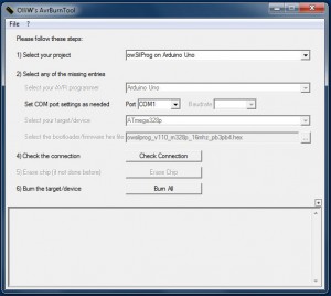
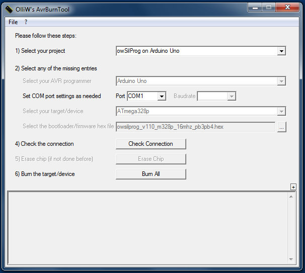
Start the Windows programm AvrBurnTool_vxxx.exe (it is located in the directory C:\owSilProg). It opens the following window:
- Set the field ‚1) Select your project‘: The drop-down box provides several options. Choose one of the ‚owSilProg‘ options, according to your Arduion board (e.g. ‚owSilProg on Arduino Uno‘ for an Uno). If your board is not listet, then please choose ‚owSilProg using other Arduino‘.
- Set the entries in the field ‚2) Select any of the missing entries‘: For the usual Arduino boards only the entry in the field ‚Port‘ needs to be set. In this case please ignore the following and jump directly to the next step! Otherwise, the drop-down box ‚Select your AVR programmer‘ should be set to either ‚Arduino @ 19200bps‘, ‚Arduino @ 57600bps‘, or ‚Arduino @ 115200bps‘ according to the baudrate, and in the field ‚Select your target/device‘ the correct processor type should be selected. Finally, in the field ‚Select the bootloader/firmware hex file‘ the proper owSilProg hex file should be selected according to the processor type, the clock frequency, and the desired pins for the programming lines C2CK and C2D.
-
Set the field ‚Port‘: Enter the USB port (or associated virtual COM port) to which the Arduino board is connected. The drop-down box lists the currently available ports. The correct port can be found as follows:
– Arduino is not connected to the PC: Click the arrow button and memorize the listed COM ports.
– Connect the Arduino board with a USB cable to the PC, and wait until the device has been registered.
– Click on the arrow button again and open the list of current COM ports. Select the newly added COM port. -
Burn owSilProg firmware ‚6) Burn the target/device‘: Pressing the Burn All button starts the actual burn process. The status window of AvrBurnTool starts displaying messages. Additionally a further window opens, which runs the program avrdude. Please wait until the message press any key to continue… appears. If all goes well, the window looks like this (for the example of an Arduino Nano):

-
Solder three cables to the Arduino Board: Finally, three cables, which will be wired to the programming pads GND (black), C2CK (red) and C2D (white) on the Silabs BESC, are soldered to the related pins on the Arduino board (to use the multiple ESC function one needs further cables, see Chapter IV). Which pins are related to C2CK and C2D is determined from the file name of the owSilProg hex file; the mark „pb3pb4“ e.g. indicates that it are PB3 and PB4. For „mini“ and „standard“ Arduino boards, the (ATmega) pins PB3 and PB4 are however electrically identical to the (Arduino) digital pins D11 and D12, and also to the MOSI and MISO pins of the ISP connector on the Arduino board. This pin assignment thus holds:
Arduino Nano, Uno, Mini, Pro Mini, Duemilanove, etc.:
pb3pb4: PB3 = digital D11 = MOSI → C2CK = red, PB4 = digital D12 = MISO → C2D = white
In most cases it will be most practical to use the GND/MOSI/MISO pins of the ISP connector, and to attach the three cables there. For an Arduino Nano (left) and Arduino Uno (right) it then may look like this:


For the mega boards it is more convennient to use the pins PB2 and PB3 (digital D51/D50) as these correspond here to MOSI and MISO. Hence, when using the owSilProg file with the mark „pb2pb3“ the C2CK and C2D lines can again be accessed exactly as before at the MOSI/MISO pins of the ISP connector. For the ArduFlyer apm2.5 board PF1 and PF0 are used (see here). - Congratulations… you did it!


The examples of an Arduino Nano and Uno were chosen above, but the instructions, with the obvious changes to the field entries and pins for the three cables, do also carry over to other Arduino boards.
If for your microcontroller and/or pin assignment the appropriate owSilProg hex file is missing, then please don’t hesitate to contact me. In general, it’s easy to create a suitable hex file!
FAQ
-
Can the Arduino be further used after having been flashed with owSilProg, i.e. does the bootlader stay intact?
Yes. The bootloader stays intact and the Arduino can be loaded with new sketches after having been flashed with owSilProg exactly as it could be before.
Trouble Shooting
- When connecting the Arduino board the first time with a PC, it is sometimes necessary to install a driver. The Arduino drivers are included since version v20120921 in the owSilProg firmware package and are located in the subdirectory ~/arduino-1.0.1/drivers/. A manual for installing the driver is e.g. Arduino UNO Windows 7 USB driver installation.
- The name of the directory which hosts the bootloader/firmware hex file MUST NOT contain spaces! Avrdude can’t handle that and will abort with an error.
- On older Arduino boards it might be neccessary in step 7 to hit the reset button (as they do not provide the auto reset feature).
- In rare cases the file libusb0.dll (or libusb0_x64.dll) seems to be needed. Since version v20130103 it is included in the owSilProg firmware package, and problems should not occur.
- In earlier firmware versions C2CK and C2D were attached to the pins PD2=D2 and PD3=D3, and it’s still said so in some manuals/tutorials on the web. Don’t get confused by that. The correct pins are indicated in the file name of the owSilProg hex file! (and if not, then you are using an outdated version)
II. BLHeliTool: Flashing the BLHeli Firmware
(instructions are for owSilProg firmware package version v20130103 or BLHeliTool v1.00, and later)
What is needed
- owSilProg programmer
- latest version of the owSilProg firmware package, or BLHeliTool files (.exe, .ini, .dev)
- BESC with Silabs microcontroller
What you need to know
For the following you should know where the pads for the three programming lines GND, C2CK, and C2D are located on your BESC. The best source of information is IMHO Steffen’s pdf document BLHeli supported SiLabs ESCs.pdf. Further you should know how you want to connect the three corresponding cables of the owSilProg programmer to these pads. The answer depends a lot on your particular case. Please consult the appropriate threads/documents, or just ask in the respective threads.
The following color coding has become common to assign cables and pads:
GND = black C2CK = red C2D = white
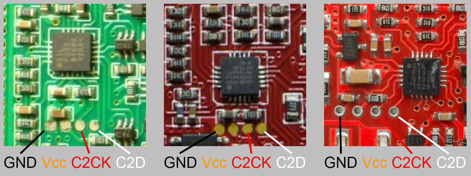
Tip: Whenever you find four pads in a row next to the Silabs chip, which is the case for many BESCs, then you can bet that they are in the sequence GND, Vcc, C2CK, C2D. Some examples are show in the picture below. Which one is GND can easily be identified from the layout of the print board, or by testing connection with a multimeter.
What to do
-
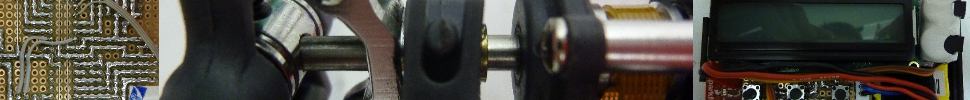
Connect owSilProg programmer and BESC: What has to be done here depends on your setup. In most cases, the three GND, C2CK, and C2D cables will be soldered to the corresponding pads on the BESC board, or an appropriate connector is build. It could look like this:

- Connect owSilProg programmer and PC: Connect the owSilProg programmer with a USB cable to the PC.
- Connect BESC with battery: How the BESC is powered depends on your specific situation, but in most cases it is powered up by simply plugging in the battery.
-
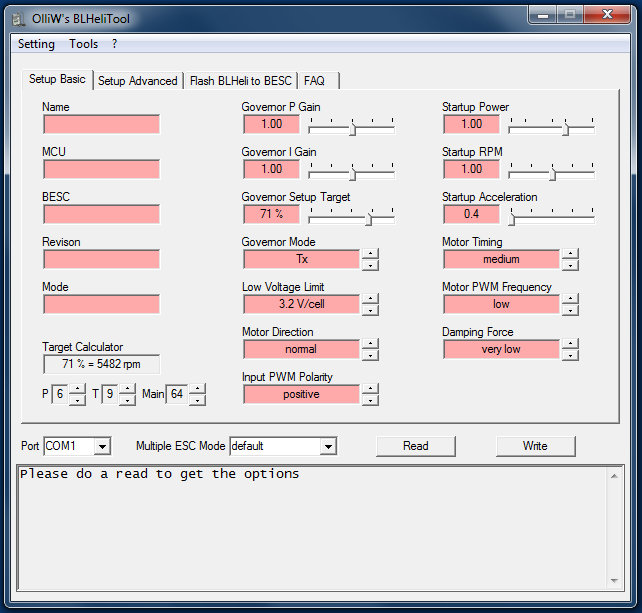
Start the Windows program BLHeliTool_vxxx.exe: The program is located in the directory where you unpacked your owSilProg package. It opens the following (or a similar) window:
-
Set the field ‚Port‘: Enter the USB port (or associated virtual COM port) to which the Arduino board is connected. The drop-down box lists the currently available ports. The correct port can be found as follows:
– Arduino is not connected to the PC: Click the arrow button and memorize the listed COM ports.
– Connect the Arduino board with a USB cable to the PC, and wait until the device has been registered.
– Click on the arrow button again and open the list of current COM ports. Select the newly added COM port. - Set the field ‚Multiple ESC Mode‘: If you’re not familiar with the multiple ESC function, then please select ‚default‘. For info on the multiple ESC function please consult Chapter IV.
-
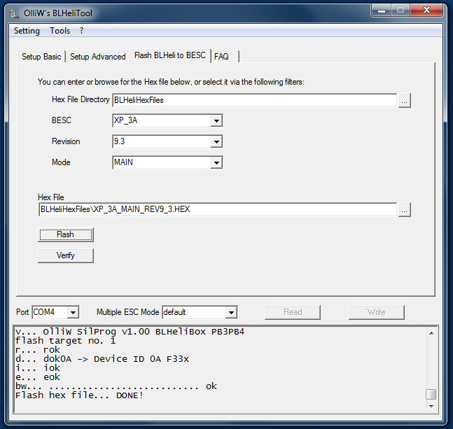
Switch to the tab ‚Flash BLHeli to BESC‘: The BLHeliTool window looks then like this (or similar):
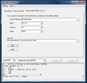
- Choose the hex file with the desired BLHeli firmware: The appropriate hex file can be determined most easily with the filters. Specify first the directory containing the BLHeli hex files in the field Hex File Directory. Usually it is BLHeliHexFiles, as preset. Then select via the drop-down boxes the BESC, revision, and mode (Main, Tail, Multi). The chosen hex file is always displayed in the Hex File field. If a hex file shall be flashed, which is not available through the filters, then enter its name into the Hex File field or press the ‚…‘ button and browse to the file.
- Flashing the BLHeli firmware: Pressing the Flash button starts the actual flashing process. The status window of BLHeliTool starts displaying messages. Please wait until the message Flash hex file…. DONE! appears – or an error message, in case something went wrong.
- Congratulations… that’s it!

FAQ
-
Is it possible to return back to the original firmware?
No. After BLHeli has been flashed, there is no way back (in principle it would be possible to flash back the original firmware, however, it is usually protected against read-out and hence not available).
Trouble Shooting
- If you get an error message, then – as a first attempt – please just retry the action once or twice. Sometimes this resolves the issue.
- ‚v… Connection to owSilProg programmer FAILED!‘: This error indicates that the USB connection via the COM port between PC and owSilProg programmer doesn’t work. In 99.99% of the cases this is not due to owSilProg/BLHeliTool/BLHeliBox, but due to a wrong COM port, missing Windows driver, etc.
- ‚d… Connection to target FAILED!‘: This error indicates that the connection between owSilProg programmer and BESC doesn’t work. In 99.9% of the cases this is not due to owSilProg/BLHeliTool/BLHeliBox, but due to a wrong or bad electrical connection between owSilProg programmer and BESC! Even when it was at first believed that everything was done right, it essentially always turned out later that it had been wrong or bad electrical connections!
- ‚d… MCU INCORRECT or connection to target FAILED!‘: This error indicates that the BESC uses a Silabs chip which is not yet supported by BLHeli or that the connection between owSilProg programmer and BESC doesn’t work reliably, similar as in the previous error. In the first case (incorrect MCU) please drop a note in any of the threads. In the second case (bad connection) the reasons for the error can be more diverse than in the previous error, and can e.g. be related to hardware details of the specific „Arduion“ board/clone.
- ‚e… Device erase FAILED!‘: This error should not happen, but unfortunately neverthelss occurs in very few cases. If it isn’t due to a „trivial“ issue, such as a weak lipo, then please drop a note in any of the threads.
- ‚bw… Block write FAILED!‘: This error should not happen, but unfortunately neverthelss occurs sometimes. If it isn’t due to a „trivial“ issue, such as a weak lipo, then it is usually a follow-up error hinting towards one of the above problems.
III. BLHeliTool: Setting the BLHeli Parameters
First, follow the instructions for Flashing the BLHeli Firmware up to the 6. step, that is:
- Connect owSilProg programmer and BESC
- Connect owSilProg programmer and PC
- Connect BESC with battery
- Start Windows programms BLHeliTool_vxxx.exe
- Set the field Port
- Set the field Multiple ESC Mode
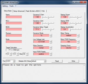
Read the parameters: The parameter values stored in the BESC can be read by pressing the Read button. The status window of BLHeliTool starts displaying messages. Please wait until the message Read… DONE! appears – or an error message, in case something went wrong. The window now displays all available parameters with their current values, and looks like this (or similar):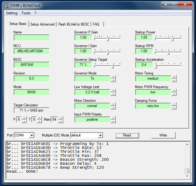
Write the parameters: The parameter values displayed in the window can be written to the BESC by pressing the Write button. The status window of BLHeliTool starts displaying messages. Please wait until the message Write… DONE! appears – or an error message, in case something went wrong.
Setting the parameters: The BLHeli parameters are available via the tabs ‚Setup Basic‘ and ‚Setup Advanced‘. BLHeli provides quite many parameters, and the partitioning leads (hopefully) to a better user experience. The usage and functioning of the various parameters is explained in Steffen’s manual BLHeli programming by TX SiLabs Rev9.x.pdf.
Trouble Shooting
- The reading and writing of the BLHeli parameters does of course work only if a BLHeli firmware has been flashed beforehand, as described in Chapter II.
IV. The Multiple-ESC Functionality
Since release v20130103, owSilProg/BLHeliTool/BLHeliBox support what I call the multiple ESC function. This simply means that one can connect up to 8 (!) BESCs to one owSilProg programmer or BLHeliBox, and handle them all at once. In some sense, you get eight, synchronized programmers in one (which I denote as programmer #1, programmer #2, …, programmer #8). This allows for convennient functions for multicopter users as well as for double-brushless conversions (main and tail) of micro helis.
The BLHeliBox fully supports the multiple ESC function, but for simplicity I will not mention it everytime in the following description of principles, which I will resctrict to the pair owSilProg programmer and BLHeliTool.
Multicopters
The advantages of the multiple ESC function are most obvious for multicopters. The installed BESCs should all behave identical, and thus should be flashed with the same firmware. Moreover any adjustment to any BLHeli parameter should be applied to each BESC. With a conventional „single-ESC“ programmer, one has to repeat every step for each BESC, and has to pay close attention to the consistency of the settings. With the mutiple ESC function this burden is taken away: All BESCs are connected to the owSilProg programmer, and BLHeliTool handles the rest.
Practically we are talking about the operations Flash, Verify, Read and Write. With one of the multicopter settings Bi Copter, Tri Copter, Quad Copter, Hexa Copter, or Octo Copter selected in the Multiple ESC Mode field, BLHeliTool will do the following:
Flash: The selected firmware (hex file) will be flashed to all BESCs with one hit of the Flash button. This is done sequentially starting with programmer #1, followed by programmer #2, until the last programmer as determined by the setting in the Multiple ESC Mode field (for a quad copter it would go until programmer #4).
Verify: The selected firmware (hex file) will be checked against the firmware loaded in a BESC for all BESCs with one hit of the Verify button. This is done sequentially starting with programmer #1, followed by programmer #2, until the last programmer as determined by the setting in the Multiple ESC Mode field.
Read: In contrast to the other operations, with a hit on the Read button only the parameters of the BESC connected to programmer #1 will be read!
Write: The parameters as specified in the two Setup tabs will be written to all BESCs with one hit of the Write button. This is done sequentially starting with programmer #1, followed by programmer #2, until the last programmer as determined by the Multiple ESC Mode. Additionally, the name, which is actually written to a BESC, is that in the Name field appended by ‚-1‚, ‚-2‚, ‚-3‚, and so on.
The BESC connected to programmer #1 is thus kind of the master BESC; only its parameters are read, and its parameters are cloned to all BESCs in a write operation. That’s how consistency of the BESCs is achieved. Note that you can watch this mechanism by inspecting the ‚read/write/flash/verify target no.X‘ outputs in the status window of BLHeliTool.
Double-Brushless Conversions (Main and Tail) of Micro Helis
In contrast to a multicopter, in a double-brushless (DBLBL) conversion, the BESCs for the main and tail motors are necessarily different, and cloning of parameter settings is hence irrelevant. However, the multiple ESC function also provides advantages for DBLBL conversions. It leads to a simpler electrical setup on the heli, since only one programming plug is needed and a simpler electrical wiring scheme results. Furthermore, handling is simplified since the decision whether the main or tail BESC should be accessed is made via a click on a drop-down box in BLHeliTool instead of swapping physically programming ports.
The BESC of the main motor is selected by simply choosing Main ESC in the Multiple ESC Mode field, and that of the tail motor is selcted by choosing Tail ESC. Importantly, the main BESC has to be connected electrically to programmer #1, i.e. C2CK(#1) and C2D, and the tail BESC to programmer #2, i.e. C2CK#2 and C2D.
Operation as Single ESC Programmer
Any BESC connected to the owSilProg programmer can be accessed individually by selecting one of the single ESC settings in the Multiple ESC Mode field. That is, if one selects single ESC no.1, then the BLHeliTool commands Read/Write/Flash/Verify invoke only programmer #1, if one selects single ESC no.2, then only programmer #2 is invoked, …., and if one selects single ESC no.8, then only programmer #8 is invoked.
The settings default and Main ESC are in fact aliases for single ESC no.1, i.e., all three invoke only programmer #1. Similarly, Tail ESC is an alias for single ESC no.2, and both invoke programmer #2.
Summary of Multiple ESC Modes
- The modes default, Main ESC and single ESC no.1 are exactly identical; they all operate on programmer #1.
- The modes Tail ESC and single ESC no.2 are exactly identical; both operate on programmer #2.
- The modes single ESC no.3, single ESC no.4, … operate on only programmer #3, #4, and so on.
- The modes Bi Copter, Tri Copter, …, Hexa Copter behave differently for Read and Write/Flash/Verify operations. Read is done by operating on only programmer #1, while Write/Flash/Verify is done by operating sequentially on all programmers from #1 up to the maximum number specified by the multicopter setting.
The described mechanisms are of course also provided by the BLHeliBox.
Electric Connections
For the above to work, one of course has first to electrically connect all BESCs to the owSilProg programmer (BLHeliBox). Each BESC needs a connection at its C2CK and C2D pads to the programmer. The programmer provides one C2D pin, which should be wired to all BESCs. The programmer however provides eight C2CK pins, called C2CK(#1), C2CK#2, …, C2CK#8. Obviously, C2CK(#1) should be wired to the C2CK pad of the BESC, which should be handled by programmer #1, C2CK#2 should be wired to the C2CK pad of the BESC, which should be handled by programmer no.2, and so on. Additionally a ground (GND) connection between the programmer and one BESC is required. If a BLHeliBox is used, and if it should be powered by the BESCs, i.e. the lipo attached to them, then also a Vcc connection is needed. Sketches of the wiring schemes look then as follows:
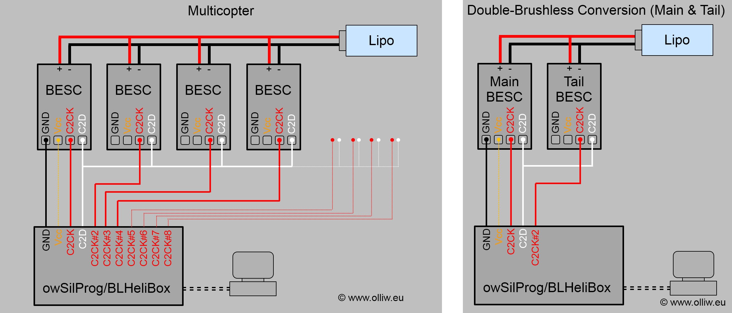
Fortunately, the owSilProg programmer allows for quite long cables (40 cm should be no problem); you can easily build a harness to connect all your BESCs to the programmer without much worries on cable lengths.
The assignment of the pins on the Arduino or BLHeliBox to the nine lines C2D, C2CK(#1), C2CK#2, …, C2CK#8 is given in the following tables. Please note that the BLHeliBoxes, which are using the standard Arduino LCD shield, as well as the Mega boards have different pin assignments.
|
Arduino Nano, Uno, Duemilanove, and so on; BLHeliBox No.3, No.4, No.5 (Arduino + LCD4884) hex files: owsilprog_v1XX_mXXX_pb3pb4.hex, BLHeliBox_v10X_lcd4884_XXX_pb3pb4.hex |
|||||||||
|---|---|---|---|---|---|---|---|---|---|
| C2CK (#1) | C2D | C2CK#2 | C2CK#3 | C2CK#4 | C2CK#5 | C2CK#6 | C2CK#7 | C2CK#8 | |
| Arduino | D11 | D12 | D10 | D9 | D8 | A2 | A3 | A4 | A5 |
| ISP | MOSI | MISO | |||||||
| Atmega | PB3 | PB4 | PB2 | PB1 | PB0 | PC2 | PC3 | PC4 | PC5 |
|
BLHeliBox No.1, No.2 (Arduino Uno + LCD Shield) hex file: BLHeliBox_v1XX_m328p_16MHz_pb3pb4 |
|||||||||
|---|---|---|---|---|---|---|---|---|---|
| C2CK (#1) | C2D | C2CK#2 | C2CK#3 | C2CK#4 | C2CK#5 | C2CK#6 | C2CK#7 | C2CK#8 | |
| Arduino | D11 | D12 | D2 | D3 | A1 | A2 | A3 | A4 | A5 |
| ISP | MOSI | MISO | |||||||
| Atmega | PB3 | PB4 | PD2 | PD3 | PC1 | PC2 | PC3 | PC4 | PC5 |
|
Arduino Mega, Mega 2560 hex files: owsilprog_v1XX_mXXX_pb2pb3.hex |
|||||||||
|---|---|---|---|---|---|---|---|---|---|
| C2CK (#1) | C2D | C2CK#2 | C2CK#3 | C2CK#4 | C2CK#5 | C2CK#6 | C2CK#7 | C2CK#8 | |
| Arduino | D51 | D50 | D49 | D48 | D47 | D46 | D45 | D44 | D43 |
| ISP | MOSI | MISO | |||||||
| Atmega | PB2 | PB3 | PL0 | PL1 | PL2 | PL3 | PL4 | PL5 | PL6 |
|
Cheapduino (Atmega8 at 16MHz) hex files: owsilprog_v1XX_m8_16mhz_pb3pb2_cheapduino.hex |
|||||||||
|---|---|---|---|---|---|---|---|---|---|
| C2CK (#1) | C2D | C2CK#2 | C2CK#3 | C2CK#4 | C2CK#5 | C2CK#6 | C2CK#7 | C2CK#8 | |
| Arduino | D11 | D10 | D9 | A0 | A4 | A5 | A5 | A5 | A5 |
| ISP | MOSI | ||||||||
| Atmega | PB3 | PB2 | PB1 | PC0 | PC4 | PC5 | PC5 | PC5 | PC5 |
V. BLHeliBox: What it is and how to use it
What is the BLHeliBox? The BLHeliBox serves several functions at once. On the one hand it is a programming box (also called programming card by some) for BLHeli Silabs BESCs, which allows us to easily set the BLHeli parameters „in-field“, independent of a PC. One just has to connect the BLHeliBox via its C2 programming lines to a BESC. The settings are then made via the keys and display. On the other hand it works also exactly like an owSilProg programmer. That is, it can be connected to a PC via USB, and using the Windows program BLHeliTool the BLHeli firmware can be flashed and the parameters be set, exactly as it has been described in Chapter II und III. The BLHeliBox thus serves three functions:
Functions of the BLHeliBox
- Flashing Silabs BESCs with BLHeli
- Setting the parameters of BLHeli BESCs via a PC using the Windows program BLHeliTool
- Setting the parameters of BLHeli BESCs „in-field“, independent of a PC
With a BLHeliBox you don’t need a separate owSilProg programmer, since it is already integrated into it (saving you the money for it). The BLHeliBox offers you however the additional advantage of checking and adjusting the parameters of a BLHeli BESC everywhere at anytime.
How is it used? Well, the operation of the BLHeliBox is simple and should be self explaining:
If it is to be used as an owSilProg programmer, then just use it exactly as you would use an owSilProg programmer… that is, connect it via USB with a PC and via the C2 programming lines with a BESC, run BLHeliTool, that’s it.
When used as a programming box the functions of the keys should become quickly clear. As regards Read BESC? and Write BESC? a comment is however at place: First switch, using the key which increases the option values, to yes, and then hold down the Select key until (after ca. 2 seconds) the Read or Write is executed (watch the display). It, btw, holds in general also in the other menus, that holding down the Select key (for ca. 2 seconds) will perform a selected action, while pressing the Select key shortly will lead you to the next menu.
The menu structure for the BLHeliBox fimrware v1.0x is as follows (shown for the example of the BLHeliBox No.5):

I did four videos for an early version of the BLHeliBox and its functions (start with part 2):
|
Part 1: Basics and Hardware |
Part 2: Setting Parameters, the BLHeliBox as Programming Box/Card |
|
Part 3: Setting Parameters, the BLHeliBox as Interface to a PC |
Part 4: Flashing the BLHeli Firmware into the BESC |
VI. BLHeliBox: Construction Manuals
(some parts only in German so far)
Unfortunately, a hardware option which would allow us to build the BLHeliBox both easily (< 10 min) AND cheaply (< $15) is not available so far. Below I present several solutions, which range from "most cheap and easy but less cool“ to „not that easy and cheap but most cool„. Personally I of course like best the last option, the BLHeliBox No.5, its extra coolness factor I found worth the extra work :). But choose yourself.
| Box | Hardware | Ranking | Costs* |
| No.1 | Arduino Uno + LCD-Keypad Shield | simple: ++, cheap: ++, cool: + | $20 |
| No.2 | Arduino Uno + LCD-Keypad Shield + Hobbyking Voltage Booster | simple: +, cheap: +, cool: ++ | $24 |
| No.3 | Arduino Uno + LCD4884 Shield | simple: +, cheap: o, cool: +++ | $30 – 30Eur |
| No.4 | Arduino Nano + LCD4884 Shield + Consumables | simple: o, cheap: o, cool: ++++ | $30 – 30Eur |
| No.5 | ArduBox with LCD4884 Module | simple: o, cheap: +, cool: +++++ | $20- $25 |
* Costs are incl. shipping
These solutions are all based on Arduino boards, which guarantees a simple build. In all cases the proper BLHeliBox firmware need to be flashed, and GND, C2CK and C2D wires to be soldered to the respective points. Here one follows exactly Chapter I, with the appropriate choice in step 4.
VI.1. Arduino Uno + LCD-Keypad Shield
Der Aufbau dieser Box ist wirklich kinderleicht, und man ist mit $20 (inkl. Versand) dabei. Copperclad @ helifreak hat hier Pionierarbeit geleistet (hier). Diese Box hat allerdings einen Nachteil. Die BLHeliBox muss natürlich mit Strom versorgt werden. Da das LCD-Keypad Shield aber mit 5 V betrieben werden muss, reicht ein 1S Lipo-Akku zur Versorgung nicht aus (das Shield funktioniert tatsächlich gerade so ab 4 V, aber das ist sehr knapp). Wer also einen 1S-Heli hat, und das werden Viele sein, der kann die Box nicht einfach über die Versorgung des Helis bzw. BESCs mitbetreiben, sondern muss der Box eine extra Versorgung spendieren, wie z.B. ein zusätzlicher 2S Lipo (dieses „Problem“ tritt nicht auf wenn die Box am PC angeschlossen ist; dann wird sie über den USB versorgt).
What is needed
- Arduino Uno
- Arduino LCD keypad shield
- three cables
- Consumables to power the box
- latest version of the owSilProg firmware package
Günstige Quellen für den Arduino Uno und das LCD-Keypad Shield sind im Appendix angegeben. Wie Ihr die Box mit Strom versorgen wollt hängt natürlich stark von eurer Situation ab. Ein einfacher Weg wäre ein extra 2S Lipo zum Anstecken an einen geeignet gefertigten Stecker.
What to do
- Flashen der BLHeliBox-Firmware. Vorgehen genau wie in Kapitel I, nur mit der Einstellungen ‚BLHeliBox on Arduino Uno + LCD Shield‘ in Schritt 4.
- Anbringen der GND, C2CK, C2D Leitungen. Drei Kabel mit den entsprechenden ISP-Anschlüssen verbinden, es kann sowohl der ISP-Stecker am Uno Board (siehe Bild Kapitel I, Schritt 8) sowie am LCD-Keypad Shield (siehe nachfolgende Bilder) benutzt werden.
- Versorgungsspannung realisieren. Da gibt es viele Möglichkeiten; eine wäre einen 2S-Lipo über einen Ein-Aus Schalter mit GND (Minus Pol) und den Vin Pad (Plus Pol) zu verbinden. Der Lipo findet evtl. sogar zwischen den beiden Boards Platz.
- Zusammenstecken der beiden Boards.
Das Ganze sieht dann z.B. so aus (leider nicht zu erkennen wie die Versorgung realisiert wurde):
photos by copperclad @ helifreak
VI.2. Arduino Uno + LCD-Keypad Shield + Hobbyking Voltage Booster
This box is perfect (but cooler ones exist). Nimic @ helifreak has done pioneering work here (link). The construction is marginally more laborious than before, one now has to master 6 simple solder joints, and costs are ca. $24 (incl. shipping). The power supply issue described in section VI.1 is solved here elegantly by using a setp-up converter (voltage booster), which converts the 1S voltage of a lipo into 5 V (or more). In comparison to the box of section VI.1. only the booster needs additionally to be installed.
What is needed
|

|
Cheap sources for the Arduino Uno and LCD Keypad Shield are given in the Appendix. In principle any booster which delivers 5 V output voltage is suitable. I like the Hobbyking Voltage Booster here (it delivers 5.2 V). $2.99 looks like a fair deal.
What to do
- Flashing the BLHeliBox firmware. Follow exactly Chapter I, except with the setting ‚BLHeliBox on Arduino Uno + LCD Shield‘ in step 4.
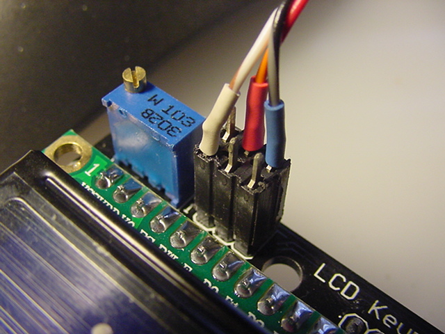
- Connect GND, C2CK, C2D wires. Solder three cables to the respective ISP connections, one can use either the ISP connector on the Uno board (see picture in Chapter I, step 8) or on the LCD keypad shield (see the following pictures).
-
Install voltage booster. The GND and Vout pins at the voltage booster are connected to the GND and Vin pads on the Uno board or the LCD keypad shield. The voltage input of the booster is connected of course to the positive pole of the lipo. Here a skecth of the wiring:

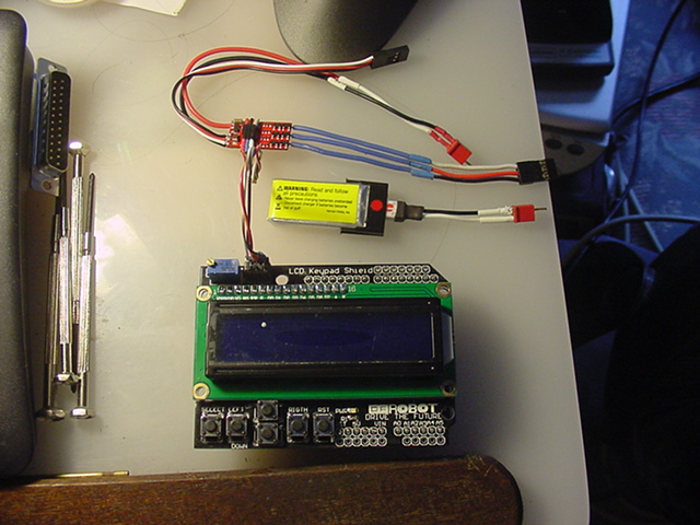
- Put together both boards.

A picture gallery showing the individual building steps in detail:


VI.3. BLHeliBox No.3: Arduino Uno + LCD4884 Shield
Diese Lösung ist perfekt, cool und leicht zu bauen, aber mit ca. $30 bis 30 Eur nicht ganz billig. Cool ist sie wegen dem graphischen Display und weil die Box deutlich kleiner/kompakter ist. Die Elekronik kann direkt aus einem 1S Lipo versorgt werden, ein Voltagebooster ist nicht nötig (der Arduino wird dann zwar ausserhalb der Spezifikation betrieben, aber das macht nichts). Wenn die Box allerdings gleichzeitig am USB und an einen Lipo angeschlossen würde, dann würde der Lipo „schnell-geladen“ werden. Dies läßt sich aber leicht vermeiden, indem eine Schottky-Diode in die plus-Versorgungsleitung vom Lipo eingebaut wird. Der Aufbau besteht also darin, vier Kabel und eine Diode anzubringen.
What is needed
- Arduino Uno
- Arduino LCD4884 shield
- Schottky diode (e.g. SB130)
- four cables
- latest version of the owSilProg firmware package
Günstige Quellen für den Arduino Uno und das LCD4884 Sield sind im Appendix angegeben. Schottky-Dioden gibt es im lokalen Fachhandel; jede ist geeignet (ich habe die Beobachtung gemacht, dass je „dicker“ die Diode desto niedriger die Durchlassspannung und desto besser für uns geeignet).
What to do
- Flashen der BLHeliBox-Firmware. Vorgehen genau wie in Kapitel I, nur mit der Einstellungen ‚BLHeliBox on Arduino Uno + LCD4884 Shield‘ in Schritt 4.
-
GND, C2CK, C2D, und Vcc Verbindunsgleitungen. In das Kabel vom Plus-Pol der BESC bzw. Lipo ist eine Schottky-Diode einzulöten (Kathode Richtung Box, Anode Richtung Lipo). Die Kabel dann mit den entsprechenden Pins des ISP-Steckers am Uno Board verbinden, siehe nachfolgendes Bild.

- Zusammenstecken der beiden Boards.

Das Ganze sieht dann z.B. so aus:


VI.4. Arduino Nano + LCD4884 Shield + Consumables
Diese Lösung benötigt etwas mehr Bastelaufwand, und etwas Geld (ca. 35Eur); die Box ist dafür im Vergleich zu den vorhergehenden Lösungen deutlich kleiner und VIEL handlicher. Anstatt eines Arduino Uno wird nun ein Arduino Nano verwendet, weil er alles hat was man braucht aber kleiner (und billiger) als ein Uno ist. Zusätzlich benötigt man ein „Adapterboard“, welches man sich selber zusammenbaut.
What is needed
|

|
Günstige Quellen für den Arduino Nano und das LCD4884 Shield sind im Appendix zu finden. Zur Schottky-Diode wurden im Kapitel IV.3 Angaben gemacht. Die weiterhin für’s Adapterboard benötigten Kleinteile sollten im lokalen Fachhandel zu finden sein.
What to do
- Flashen der BLHeliBox-Firmware. Vorgehen genau wie in Kapitel I, nur mit der Einstellungen ‚BLHeliBox on Arduino Nano (w m328p) + LCD4884 Shieldd‘ in Schritt 4.
- Adapterboard basteln. Hierzu wird der Arduino Nano auf eine Leiterplatte gelötet, und Verbindungen zu entsprechend angebrachten Steckerleisten hergestellt. Die nachfolgende Bilderreihe gibt eine Anregung.
- Zusammenstecken der Boards.
Diese Bilderreihe zeigt meinen Aufbau. Ich habe mir noch den Spass gemacht und habe das ganze mit passend zugeschnittenem, dicken Papier umhüllt. Macht die ganze Box noch einiges touchier:


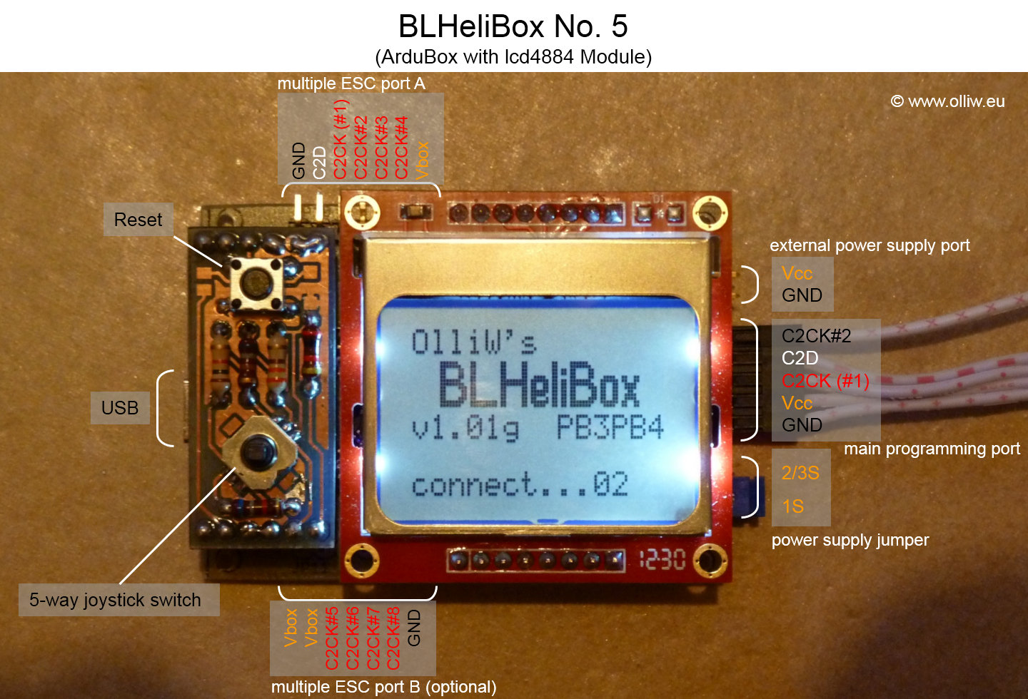
VI.5. BLHeliBox No.5: ArduBox with LCD4884 module
This is certainly so far the most cool, compact, best, and in comparison cheapest solution! One uses simply an ArduBox, which provides everything needed, and flashes the BLHeiBox firmware. The BLHeliBox No.5 provides all connections required for making full use of the multiple ESC function, is ideally suited for double-brushless conversions (main&tail) of micro helis, and allows to select between 1S and 2/3S power supplies via a jumper.
What is needed
- ArduBox with LCD4884 module
- latest version of the owSilProg firmware package
Currently one has to build the ArduBox oneself, but the ArduBox may become available for purchase in the near future (not by me, but someone else). For all infos on the ArduBox, please see here.
What to do
- Flashing the BLHeliBox firmware. Follow exactly Chapter I, except with the setting ‚BLHeliBox No.5 (Arduino Nano w m328p + LCD4884 module)‘ in step 4.
Here’s a detailed view on the BLHeliBox No. 5, with all provided connections/ports:
VII. The Bluetooth Extension
The owSilProg programmer, the various BLHeliBoxes and BLHeliTool can be used very easily together with a Bluetooth adapter. That is, with a Bluetooth module connected to the owSilProg programmer and/or BLHeliBox the communication with BLHeliTool is wireless. When everything is set up, which is done quickly with the developped methods, things run that smooth that one actually doesn’t recognize the wireless operation (except of course of the missing cable). The usage is exactly as before, without the need of any special actions.
Which Bluetooth module?
I am using the bluetooth-serial module everyone is using for this purpose. Especially I got the JY-MCU BT module with voltage regulator. Possible sources you find in the Appendix.
Connecting the Bluetooth module to the owSilProg programmer or BLHeliBox
The bluetooth module is connected via a diode (any diode does it, e.g. 1N4148) to the Rx and Tx pins (digital D0 and D1) of the Arduino, as shown in the scheme.
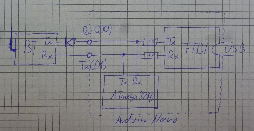
The resistor in the Tx connection to the USB adapter is very important for the correct functioning. However, it rarely has to actually be installed explicitely. The Arduino boards with a USB connector come with the drawn resistors already implemented, and you hence don’t have to worry further about them. Even otherwise they are not needed, at least with USB-serial adapters with FTDI chip. So, in praxis you only need the diode.
Setting up Win7 for using the Bluetooth module
Follow this description, up to the point where teraterm gets involved: http://www.hobbytronics.co.uk/bluetooth-module-connection
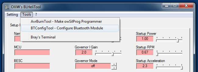
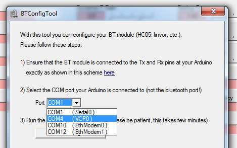
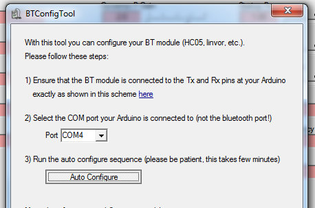
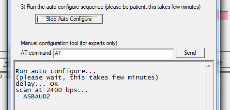
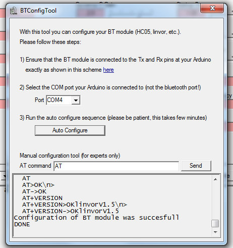
Configuring the Bluetooth module
This is done using the BTConfigTool, which is integrated into BLHeliTool; it does the configuration fully automatically. The steps in pictures:
Further infos
http://www.rcgroups.com/forums/showpost.php?p=23960212&postcount=437
Appendix: Sources of Supply
Arduino Nano
Germany:
- 14.90Eur (+ 3,50Eur shipping) at lipoly.de
Overseas
- $10.38 (incl. shipping) at r_cube_station (ebay)
- $10.99 (incl. shipping + USB cable) at Dealextreme
- $11.50 (incl. shipping) at haoyu_electronics (ebay)
- $9.29 (+ $2.99 shipping) at Hobbyking
- various Asian ebay dealers: ebay.de
Arduino Uno/Uno R3
- $10.82 Uno or $14.20 Uno R3 (+ $2.99 shipping) at Hobbyking
- $12.49 Uno R3 (incl. shipping + USB cable) at MITAO E-mart (AliExpress), link
- $13.96 Uno (incl. shipping) at uzone2012 (ebay), link
- $14.72 Uno (incl. shipping + USB cable) at jk_parts (ebay), link
- $15.20 Uno R3 (incl. shipping + USB cable) at Dealextreme, link
- various other Asian ebay dealers
Cheapduino
- $19.90 for 5 pieces (+ shipping) at DFRobot
Arduino LCD-Keypad Shield
- $6.90 (incl. shipping) at Dealextreme, link
- ca $7 from Asian ebay dealers (link)
- Hobbyking $8.32 link (+ $2.99 shipping)
Arduino LCD4884 Sield
Germany:
- 15.88Eur (incl. shipping) at profit_vanity (ebay)
Overseas
- 11.99Eur (incl. shipping) at profit_vanity (ebay)
- $21.67 (incl. shipping) buychina
- ca. $20 from various dealers (use google)
Arduino Uno + LCD4884 Sield Combo
Germany:
- 26.88Eur (incl. shipping) at profit_vanity (ebay)
Overseas
- 23.99Eur (incl. shipping) at profit_vanity (ebay)
- $32.99 (incl. shipping) at trade_spotting (ebay)
Bluetooth Module (JY-MCU, HC05)
Europe:
- 8.50Eur (incl. shipping) at hillfly3389 (ebay) (UK)
- 8.29Eur (+ 0.99Eur shipping) at newlaunch (ebay) (UK)
Overseas
- $8.20 (incl. shipping) at Dealextreme, link
- ca. $10 from various ebay dealers (use google)
Other Sources
- This thread might provide further useful sources China SUPER Bauteile-Schnäppchen Thread @ www.micokontroller.net
109 Kommentare